

From Dual-Hook Synchronization to Hoisting Systems: A Comparison of Electrical and Mechanical Axis Solutions for Custom Cranes
📌 Synchronization accuracy of the dual-hoist-point synchronous lifting system: For the electrical-axis configuration, the angular deviation is less than 0.1 degrees (EtherCAT/PROFINET servo bus); for the mechanical-axis configuration, the deviation is less than 1 degree (mechanical drive shaft + coupling).Electric drives are suitable for long-distance (greater than 15 meters) and high-speed synchronized applications, while mechanical drives are suitable for medium- to short-distance applications requiring high reliability. Krude Heavy Industry has accumulated system design experience with both solutions through custom projects involving the handling of long materials and the lifting of oversized workpieces. This article explores the topic from three perspectives: the principles of synchronization, a comparison of the two solutions, and engineering implementation.
The dual-lifting-point synchronous hoisting system is one of the most common special design requirements for custom-built cranes. It is primarily used for handling long materials (such as steel pipes, steel plates, and bridge sections), oversized workpieces (such as molds and pressure vessels), and scenarios involving coordinated operation of two trolleys. When a crane needs to lift a workpiece simultaneously from two lifting points, the hoisting speeds at both points must be perfectly synchronized; otherwise, the workpiece may tilt, become off-center, or even fall. There are two primary engineering solutions for achieving synchronization: electrical synchronization and mechanical synchronization, each with its own advantages and disadvantages in terms of precision, cost, maintenance, and scope of application. In its custom design process, Krude Heavy Industry selects the appropriate solution based on a comprehensive evaluation of the workpiece’s length, weight, duty cycle, and operating environment.
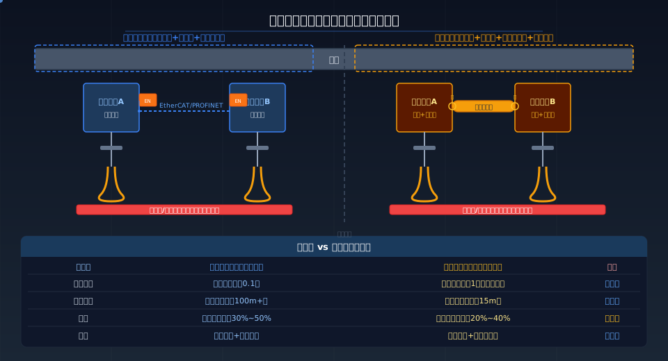
Principles and Design of Electrical Shaft Synchronization Solutions
Electronic Line Shaft refers to the synchronization of the position and speed of two or more hoisting motors via a servo motor, encoder, and fieldbus, without the need for a physical drive shaft connection. At the core of the system, servo drives exchange position commands and actual position feedback via real-time communication buses such as EtherCAT or PROFINET. Each drive operates with independent closed-loop position and speed control, but the setpoints are synchronized via the bus. In its engineering applications, Krude Heavy Industry employs two synchronization strategies: master-slave mode and virtual line shaft mode. In master-slave mode, one drive serves as the master shaft, and the other drives follow the master’s position commands; in virtual line shaft mode, the controller calculates virtual position commands and distributes them to each drive, without relying on a physical line shaft.
The key parameters of the electric-axis solution are the synchronization period and communication jitter. The EtherCAT bus synchronization period can reach 100 microseconds, with communication jitter less than 1 microsecond; the positional deviation between the two motors can be controlled within one pulse equivalent of the encoder. Taking a 17-bit absolute encoder as an example, the angular deviation of the motor shaft is less than 0.1 degrees. For heavy-load hoisting applications, this level of accuracy is sufficient to ensure that the horizontal deviation of the workpiece during synchronized lifting at dual lifting points is less than L/1000.
Principles and Design of Mechanical Shaft Synchronization Solutions
Mechanical shaft synchronization refers to the physical connection of the output shafts of two or more gear reducers via a mechanical drive shaft (synchronizing shaft) and couplings, so that all hoisting drums rotate at the same speed, thereby achieving forced synchronization. Mechanical shaft synchronization does not require a communication bus and does not rely on the real-time performance of electrical control systems; its reliability depends entirely on the machining precision and assembly quality of the mechanical components. In the mechanical shaft configuration, variable-frequency asynchronous motors (non-servo) are typically used. The gearboxes are connected to the synchronizing shaft via rigid couplings or flexible pin couplings, with the output shafts of the electric hoist gearboxes located at each end of the synchronizing shaft.
Key design considerations for mechanical shaft synchronization include: verification of the torsional stiffness of the synchronized shafts (the torsional angle is generally kept within 0.5 degrees/m), coupler selection (elastic couplers compensate for installation misalignment), and support bearing arrangement (one intermediate support every 2–3 m). The length of a synchronous shaft generally does not exceed 15 m. When the length exceeds 15 m, torsional deformation of the shaft system increases and bearing arrangements become more complex; in such cases, an electric shaft solution should be prioritized. The cost advantage of mechanical shafts is most evident in medium- to short-distance applications (5–10 m), where the material costs of the synchronous shaft and couplings are significantly lower than those of two separate servo drive systems.
A Comprehensive Comparison of Electrical-Axis and Mechanical-Axis Solutions
| Dimensions of Comparison | Electrical Axis (Servo Bus Synchronization) | Mechanical Shaft (Synchronous Mechanical Drive Shaft) |
|---|---|---|
| Synchronization Accuracy | Angle deviation less than 0.1 degrees | Angular deviation less than 1 degree (including gear backlash) |
| Distance Limit | Unlimited (bus length 100 m+) | 15 meters or less (excessive length causes significant torsional deformation) |
| Cost Comparison | The servo system costs approximately 30% to 50%. | Mechanical parts are about 20% to 40% cheaper. |
| Maintenance Requirements | Remote Diagnostics + Parameter Adjustment—No Mechanical Maintenance Required | Regular Lubrication + Coupling Clearance Inspection + Shaft Alignment |
| Reliability | Relies on the reliability of the communication bus; the system stops when the bus connection is lost | Purely mechanical forced synchronization, independent of the electrical system |
| Applicable Scenarios | Long distance (greater than 15 m), high precision, multiple suspension points (3+) | Short- to medium-range, high reliability requirements, simple maintenance |
| Debugging Complexity | Servo parameter tuning + bus synchronization configuration—requires a professional | Mechanical Alignment + Coupling Assembly, Short Commissioning Cycle |
| Scalability | Can be easily expanded to three or more suspension points; simply configure via the software. | Adding a suspension point requires extending the synchronous shaft, which complicates the structure. |
|
Synchronization Accuracy The electrical axis must be within 0.1 degrees, and the mechanical axis within 1 degree. When lifting long materials, a 1-degree angular deviation corresponds to an end-of-workpiece deviation of approximately 175 mm over a 10-meter length; this must be strictly controlled. |
Control Method Electrical axes: EtherCAT/PROFINET bus, 100-microsecond synchronization cycle. Mechanical axes: Forced mechanical interlock, no controller intervention required. |
Effective Range There is no upper limit on the distance for electrical axes (bus length of 100 m or more). For mechanical axes, a length of less than 15 m is recommended; if the length exceeds 15 m, the torsional deformation of the shaft system will exceed the limit. |
|
Motor Selection Electrical axes: servo motor + absolute encoder. Mechanical axes: an inverter-driven asynchronous motor is sufficient; a servo motor is not required. |
Failure Modes Electrical shaft: Automatic shutdown and alarm upon bus disconnection. Mechanical shaft: Increased clearance due to coupling wear or damage to the keyway. |
Project Case Studies Krud Heavy Industries uses an electric-axis solution for steel plate lifting equipment at steel mills (18-meter workpieces) and a mechanical-axis solution for port machinery (8-meter short-span applications). |
Engineering Selection Recommendations
Krud Heavy Industries follows the following principles when selecting non-standard dual-lifting-point synchronous hoisting systems: When the workpiece length exceeds 15 meters or the number of lifting points is three or more, the electric-axis solution is preferred; for workpieces between 5 and 15 meters in length where the operating environment requires simple maintenance, the mechanical shaft solution is preferred; for workpieces shorter than 5 meters, a single electric hoist combined with a balancing beam is sufficient, and dual-lifting-point synchronization is not required. Although the initial investment for the electric-axis solution is higher by 30%–50%, it offers better overall cost-effectiveness than the mechanical-axis solution in long-distance and high-precision applications. For more information on custom crane designs, please refer toThe Complete Guide to Customizing Non-Standard Cranes。
The design is based on the requirements for synchronized hoisting mechanism design specified in GB/T 3811-2008, “Code for Design of Cranes,” as well as the IEC 61800-7-201 communication standard for servo drive systems. Safety protection requirements for synchronized hoisting systems mandate that each lifting point be equipped with an independent overload limiter and limit switch. When a lifting point is overloaded or reaches its limit, the system must issue an audible and visual alarm and automatically stop the hoisting operation. All synchronized hoisting systems provided by Krude Heavy Industry for custom projects have been verified through type testing.
Frequently Asked Questions (FAQ)
Q: What is the required accuracy for synchronized lifting with two lifting points?
Answer: Synchronization accuracy depends on the workpiece length and the allowable tilt angle. Generally, the height deviation at the lifting point should not exceed L/1000 of the workpiece length. Taking a 10-meter-long steel plate as an example, the allowable deviation is 10 mm, which corresponds to an angular deviation of approximately 0.3 degrees for the hoisting motor shaft. The electrical axis solution (less than 0.1 degrees) fully meets this requirement, while the mechanical axis solution (less than 1 degree) is also sufficient for short workpieces. For applications with stricter requirements, a laser rangefinder can be installed to monitor the workpiece’s levelness in real time.
Q: What should I do if the electrical shaft bus breaks?
Answer: The safety design of an electric-axis system must account for bus disconnection. In the event of a bus disconnection, each drive immediately enters a safe stop state upon detecting a communication timeout (typically set to 50–100 ms); all motors stop simultaneously and the brakes remain engaged. The system design also includes a hard-wired emergency stop circuit as a backup. In accordance with the GB/T 3811 and IEC 61800-5-2 standards, the safety stop function must be rated at SIL 2 or higher. Before shipment, Krude Heavy Industry’s electric axis systems undergo validation testing that simulates a bus disconnection.
Q: How do you verify the torsional stiffness of a mechanical synchronous shaft?
Answer: The torsional angle of a synchronous shaft is calculated using the formula θ = T * L / (G * J), where T is the transmitted torque (Nm), L is the shaft length (mm), G is the shear modulus (approximately 79.3 GPa for steel), and J is the polar moment of inertia (mm⁴). Based on engineering experience, the torsional angle should be kept below 0.5 degrees/m. After the shaft diameter is preliminarily selected based on the transmitted torque and torsional strength, it must be verified for fatigue strength (taking into account startup impact and alternating forward and reverse rotation). For the synchronous shaft material, quenched and tempered 45 steel or 40Cr is recommended.
Q: Can an old crane be modified for dual-point synchronized lifting?
A: Yes, it can be retrofitted. The difficulty of converting an old crane to a dual-hoist-point synchronous system depends on the original electrical system. If the original system uses variable-frequency control and has a PLC communication interface, the electrical retrofit only requires replacing the drives with servo drives equipped with bus interfaces and installing encoders, while retaining the original motors and gearboxes. If the original system is contactor-controlled, we recommend a complete replacement with a variable-frequency/servo system and a PLC control cabinet. Krude Heavy Industry offers retrofit solutions for synchronized operation of older cranes, with a typical retrofit cycle of 2 to 4 weeks. For more information on retrofitting older cranes, please refer toCustomization Solutions for Older Cranes。
