Crane VFD Speed Control & Energy Feedback Braking

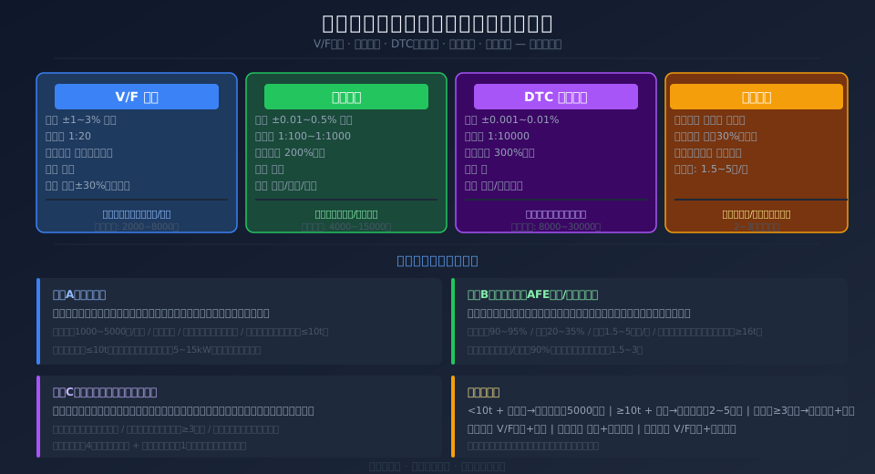
Three VFD control methods for overhead crane speed control: V/F control (accuracy ±1–3%, speed ratio 1:20, lowest cost) — Kelude recommends for small-to-medium cranes; Vector Control (accuracy ±0.01–0.5%, 1:100–1:1000) — suited for positioning cranes; DTC (Direct Torque Control) (accuracy ±0.001%, 1:10000) — for precision servo applications. Braking options: resistor braking (approx. $740 per unit) for cranes up to 10t; energy feedback (approx. $3,000–$7,400 per unit) saves 20–35% energy, ideal for heavy-duty frequent start-stop cycles; shared DC bus for multi-crane coordinated operation.

When the hoisting mechanism lowers a load, the motor operates in regenerative mode, and the frequent acceleration and deceleration of the crane bridge and trolley also generate significant regenerative energy. The VFD control method (V/F, Vector, or DTC) determines speed regulation accuracy and low-frequency torque, while the braking scheme (resistor, regenerative feedback, or shared DC bus) dictates how regenerative energy is handled. Poor selection can lead to load slipping during hoisting, jerky travel motion, or substantial energy waste. This article compares the engineering selection criteria for crane electrical control systems across these two dimensions — VFD control methods and braking schemes.

Crane VFD speed control and regenerative braking selection guide — V/F, Vector, and DTC control methods plus braking resistor, energy feedback, and shared DC bus braking options

VFD Control Method Comparison for Crane Hoists

The hoisting mechanism demands three things from a VFD: high torque at low frequencies (≥150% rated torque at 0 Hz to prevent load slipping), a wide speed range (creep speeds below 0.1 m/min for precise load positioning), and fast braking response (rapid reverse-torque build-up during emergency stops). The travel mechanisms (bridge and trolley) require smooth speed regulation, adjustable acceleration/deceleration times, and synchronization across multiple motors. Each of the three control methods below offers distinct advantages.

V/F control (voltage/frequency ratio control) is an open-loop method that maintains a constant voltage-to-frequency ratio to regulate motor speed. It offers the simplest architecture and lowest cost, but suffers from weak low-frequency torque (only 50–70% of rated torque between 0–5 Hz) and limited speed accuracy (±1–3%). This makes it suitable for the travel mechanisms of small-to-medium cranes where precision is not critical — V/F control fully meets the requirements, and each VFD saves approximately $300–$740 in upfront cost.

Vector Control (VC) uses coordinate transformation to control an asynchronous motor with the same precision as a DC motor, independently regulating both magnetizing current and torque current. It delivers over 200% rated torque at 0 Hz and achieves speed accuracy of ±0.01–0.5%. Closed-loop vector control with an encoder is the standard configuration for crane hoisting mechanisms — high torque at low frequency ensures full-load lifting without load slipping, and high-precision speed regulation enables creep-speed positioning (0.1 m/min). Kelude equips its hoisting mechanisms with vector control as standard, using incremental encoders with 1024 PPR.

DTC (Direct Torque Control) is an ABB-patented technology that directly controls the motor's stator flux and torque, delivering the fastest response time (1–5 ms), up to 300% torque at 0 Hz, and speed accuracy of ±0.001%. DTC achieves high-precision control without an encoder (sensorless DTC), making it the highest-tier option for precision servo control on overhead cranes. The cost is higher (roughly 2–4 times that of V/F control), and it is best suited for unmanned overhead crane applications requiring precise position control. Kelude recommends the ABB ACS880 series DTC drive for its high-end configurations.

Braking Scheme Engineering Comparison for Regenerative Energy

Regenerative energy handling is the core of energy efficiency in crane electrical control systems. The potential energy recoverable when the hoist lowers a load accounts for 30–40% of total lifting energy consumption. Feeding this energy back to the grid (or absorbing it via other cranes on the same bus) can significantly reduce operating costs. The choice of braking scheme depends on lifting capacity, duty cycle, electricity rates, and payback period.

The selection among the three braking schemes hinges on lifting capacity, operating frequency, and capital budget. Braking resistors dissipate regenerative energy as heat — the most traditional and reliable approach, but with the drawbacks of energy waste and resistor cabinet heat buildup. A single hoist/lower cycle on a 10t crane generates approximately 50–80 kJ of heat in the braking resistors; in summer, multiple cranes operating simultaneously in a factory building can raise ambient temperature by 3–5°C. Energy feedback (AFE — Active Front End) uses an active rectifier to shape regenerative energy into a sine wave synchronized with the grid in frequency and phase, achieving 20–35% energy savings. However, it requires additional feedback units and input reactors, increasing the initial investment.

Shared DC bus delivers the best results in multi-crane coordinated operations — regenerative energy from one crane lowering a load is consumed directly by an adjacent crane lifting a load, with energy circulating internally on the DC bus. Field measurements show that with four cranes operating simultaneously, a shared DC bus achieves approximately 15–25% energy savings; adding one feedback unit to absorb excess energy raises this to 30–35%. The payback period depends on duty cycle — in frequent start-stop applications (e.g., steel mill continuous casting bays), payback is shortest at roughly 1 year; in typical workshops, it extends to about 2 years. Kelude provides investment return analysis reports to support customer decision-making.

← Scroll left / right to view full table →
Comparison Parameter Braking Resistor Energy Feedback(AFE) shared DC bus
PrincipleRegenerative Energy Resistance Thermal EnergyRegenerative Energy IGBTInverter GridRegenerative Energy Consumption by Other Cranes
Energy Recovery Efficiency0%(Total Heat Dissipation)90~95%20~70%(Multi-Crane Dependency Synchronization)
Energy Saving Effect0%20~35%10~25%
Equipment Cost1000~5000CNY/Set1.5~510K CNY/Set3000~8000CNY/Multi-Crane Dependency(Reactor)
Thermal Management RequirementHigh(Resistor cabinet Ventilation and Heat Dissipation)Low(High Feedback Efficiency, Low Heat Generation)Medium
Payback PeriodN/A1.5~3Year(Frequent Lifting/Lowering Operations)1~2Year(Multiple Workshop Duty-Cycle Complementary Operations)
Applicable Lifting Capacity≤10t≥16t(Recommended)≥3Unitoverhead crane Fleet
Applicable Applications FrequencyA1~A4A5~A8A3~A6
Kelude Recommendation≤10tStandard Configuration, Cost-EffectiveSteel Mill/Casting/Metallurgical Preferredcollaborative dispatching system Standard Configuration

Hoist Inverter Parameter Tuning for Overhead Cranes

Parameter tuning on the hoist inverter directly affects lifting safety and operational efficiency. The core parameters fall into five categories: Motor parameters — rated power/voltage/current/speed/power factor, measured automatically via inverter auto-tuning (static tuning takes 5–10 seconds, dynamic rotational tuning 30–60 seconds). For overhead crane hoisting mechanisms, dynamic rotational tuning is recommended (motor decoupled from the load, running unloaded) to measure stator resistance, rotor resistance, leakage inductance, and magnetizing inductance — this delivers 3–5 times higher accuracy than static tuning. For a Siemens G120 with encoder-based Vector Control, the nameplate input parameters are: motor power = 11kW, rated current = 22A, rated speed = 1460rpm, power factor = 0.82.

Acceleration and deceleration time parameters — Set hoist acceleration time to 3–6 seconds (too short causes load slipping or overcurrent trips; too long hurts productivity), and deceleration time to 3–8 seconds (too short causes regenerative overvoltage; too long affects Positioning Accuracy). The deceleration time constraint is that DC bus voltage must not exceed 750VDC (380VAC rectified peak ≈ 537V; regenerative energy raises the bus, and the Braking Resistor engages at 680V). Maximum regenerative energy occurs during full-load lowering, so deceleration time must be calculated based on braking unit power and duty cycle. Kelude Heavy Industry standard: 10t hoist — 4s acceleration / 5s deceleration, with Braking Resistor power sized at 50% of motor power.

Low-frequency torque boost and anti-load-slipping parameters — In V/F control mode, enable low-frequency torque boost (set P1300 to 2-point boost, with boost voltage at 0Hz equal to 10–15% of rated voltage); in Vector Control mode, enable zero-speed torque hold (set P1501 to hold 150% of current torque). Brake control sequence: upon receiving the start command, the inverter first builds excitation current, raises output frequency to 3Hz, then opens the Brake and continues accelerating to the target frequency. Stop sequence: the inverter decelerates to 0.5Hz, waits 100ms to confirm motor standstill, then closes the Brake. Mismatched timing is a common cause of Load slipping. Kelude Heavy Industry hoist control programs come pre-loaded with standard timing parameters; on-site, only the wait time needs adjustment based on Brake response speed (mechanical Brake: approx. 200–400ms; Hydraulic brake: approx. 100–200ms).


Energy Feedback System ROI Analysis

The economic benefit of an Energy Feedback system depends on three factors: hoist cycle frequency, load factor, and local electricity rates. Taking a 32t crane in a continuous casting bay as an example: 18 operating hours per day, 15 hoist/lower cycles per hour on average, 60% average load factor, 45kW motor power. Regenerative energy released during one lowering cycle ≈ 45kW × 0.6 × 0.7 (efficiency coefficient) × (full-stroke lowering ≈ 15 seconds / 3600 hours) = 0.079kWh. Daily: 15 cycles/hour × 18 hours × 0.079kWh = 21.3kWh/day; annual (330 working days) × 21.3kWh = 7,029kWh/year. At an industrial electricity rate of 0.8 CNY/kWh, annual savings per crane ≈ 5,623 CNY (~$830).

The feedback unit investment is approximately 25,000 CNY (~$3,700) (including AFE feedback unit + input Reactor + EMC Filter + Installation & Commissioning), giving a payback period = 25,000 / 5,623 ≈ 4.4 years. However, with a shared DC bus, the actual energy-saving rate of the feedback unit can be raised to 30–35%. If 4 cranes share one DC bus with a single feedback unit, the investment is about 50,000 CNY (~$7,400) (feedback unit 25,000 CNY + DC Reactor and busbar ≈ 25,000 CNY). Total annual savings: 4 cranes × 7,029kWh × 1.3 (shared-bus efficiency coefficient) = 36,551kWh/year × 0.8 CNY = 29,241 CNY/year (~$4,330), with a payback period = 50,000 / 29,241 ≈ 1.7 years. For higher hoist frequencies (A7~A8 duty, 30+ cycles per hour), a single crane saves approximately 14,000kWh/year ≈ 11,000 CNY (~$1,630), bringing the feedback unit payback to about 2.3 years.

Kelude Heavy Industry offers a free 7-day on-site energy measurement service before signing an Energy-Saving Retrofitting contract — a power quality analyzer (Fluke 435 II) is installed on the inverter DC bus to measure actual regenerative energy and feedback potential, followed by an energy consumption analysis report and investment payback assessment. Construction proceeds only after customer approval, and the energy-saving rate is verified by on-site measurement during Acceptance. Kelude Heavy Industry has 30+ feedback systems operating in steel mills and foundries, with average measured energy savings of 25–35% (AFE solution) or 15–25% (shared-bus solution) — all meeting or exceeding pre-assessment values.

Kelude Standard VFD Configurations for Overhead Cranes

Kelude Heavy Industry crane VFD control systems are classified into three standard configuration grades based on Lifting Capacity and duty cycle: Economy Grade (A1~A3 duty, ≤10t) — Hoisting mechanism with V/F control + Braking Resistor (cabinet-top cooling fan), Crane Bridge/Trolley with V/F control + Braking Resistor, standard Siemens G120 or Inovance MD280 series VFDs. Braking Resistor power is sized at 30–50% of Hoisting Motor power, mounted on top of the electric control cabinet; the Resistor cabinet includes a temperature switch (95°C alarm / 110°C cuts the hoist circuit).

Standard Grade (A4~A5 duty, 10–32t) — Hoisting mechanism with Vector Control (with Encoder, meeting speed control accuracy requirements per JB/T 9052-2015 Section 4.2.1) + Energy Feedback unit; Crane Bridge/Trolley with V/F control + Braking Resistor. The Hoist Inverter is standard Siemens G120 (vector type) or Inovance MD880, with an incremental Encoder at 1024 PPR (HTL signal). The feedback unit Installed Capacity is sized at 50–80% of Hoisting Motor power. The control system includes a PLC + 7-inch Touch Screen (HMI) displaying operating parameters and fault logs. Kelude Heavy Industry has delivered 120+ Standard Grade systems across automotive, steel, building materials, and other industries.

Premium Grade (A6~A8 duty, ≥32t or frequent start/stop) — Hoisting mechanism with Direct Torque Control (DTC) + AFE Energy Feedback + shared DC bus (for multi-crane installations); Crane Bridge/Trolley with Vector Control + Energy Feedback. The Hoist Inverter is standard ABB ACS880 (DTC) or Siemens S120, with an absolute Encoder (EnDat or SSI, single-turn + Multi-turn). The AFE feedback unit Installed Capacity is sized at 100% of Hoisting Motor power. The shared DC bus solution includes Insulation monitoring (bus-to-ground Insulation ≤ 500kΩ triggers an alarm). Kelude Heavy Industry has delivered 30+ Premium Grade systems to steel mills and foundries, with measured energy savings of 25–35%.


← Scroll left / right to view full table →
Comparison ParameterV/FControl(Economy)Vector VC (Standard)DTCDirect Torque(Premium)
Speed control Accuracy±1~3%±0.01~0.5%±0.001~0.01%
Speed control Ratio1:201:100~1:10001:10000
0HzDirect Torque50~70%(Compensation Required)200%(Closed-Loop Vector)300%(None Sensor)
EncoderNot RequiredIncremental1024Pulses per revolution (PPR)Not Required
Response time50~100ms10~30ms1~5ms
Frequency Inverter / VFDEquipment Cost2000~5000CNY4000~15000CNY8000~30000CNY
overhead crane ApplicableCrane Bridge / Long Travel/Cross Travel / Trolley TravelHoisting mechanism(Standard Configuration)Precision Servo Positioning

Frequently Asked Questions

Q: Why is low-frequency torque critical for overhead crane hoisting mechanisms, and how do you prevent load slipping?

A: During start-up and stopping, the motor speed approaches zero (low-frequency state). If the VFD cannot deliver sufficient low-frequency torque, the hook will drift downward—a condition known as load slipping. V/F control suffers severe torque attenuation in the 0–5 Hz range (output drops to only 50–70% of rated torque), so low-frequency torque compensation or vector control is essential. Vector control delivers over 200% rated torque even at 0 Hz, completely eliminating load slipping. Kelude hoisting mechanisms come standard with vector control VFDs (Siemens G120 or Inovance MD880), providing ≥180% torque at 0.5 Hz. If an existing V/F drive is experiencing load slipping, you can increase the low-frequency compensation voltage in the drive parameters (P13002/3-point boost), but compensation has its limits—vector control is the recommended choice for low-frequency duty.

Q: What grid requirements must be met for an active front end (AFE) energy feedback unit?

A: The AFE regenerative unit requires stable grid voltage (fluctuation ≤±10%), low harmonic content (THD ≤5%), and a reliable neutral-ground connection. During operation, the unit injects harmonics into the grid (high-frequency components generated by IGBT switching), so an input reactor (3% voltage drop) and EMC filter must be installed. In theory, the AFE can feed energy back to any three-phase grid, but we recommend measuring background grid harmonics before installation. For grids with significant harmonic pollution, add an active filter (APF). Kelude AFE packages come standard with an input reactor plus EMC filter, keeping regenerative current THD ≤5% without interfering with other equipment on the same bus. Utility requirements: same standard as solar grid-tie systems—no approval needed when regenerative power is ≤20% of transformer capacity.

Q: How is a shared DC bus routed across a fleet of overhead cranes?

A: The DC bus positive and negative terminals of each crane's VFD are connected to a common DC bus bar via conductor rails or cables. Routing options: ① Cranes on the same bay—lay a DC bus conductor rail (with insulated sheath) along the crane rail, with each crane drawing power through carbon brushes; ② Cranes in different bays—connect via trench-laid cables with DC reactors added to prevent cross-bay circulating currents. Each VFD's DC bus includes a fast-acting fuse (to isolate a single-unit fault without affecting the entire network) and a DC reactor (to suppress current ripple). The common bus voltage is set to 540 VDC (nominal value after rectifying 380 VAC). When braking on one crane pushes bus voltage above 720 V, the regenerative unit or braking resistor engages. Kelude has deployed shared DC bus solutions across 4 multi-crane coordination projects, with the longest cross-bay distance reaching 120 m, interconnecting 4–8 cranes per system, and zero failures over 2 years of operation.

Q: What should you watch out for when retrofitting an old relay-controlled crane to VFD control?

A: Key considerations for relay-to-VFD retrofits: ① Motor compatibility—verify the motor's insulation class (≥Class F). Older motors (e.g., 1980s JZR series) have high rotor resistance and poor low-frequency characteristics; we recommend replacing them with YVP variable-frequency motors. ② Brake control—the VFD start/stop sequence must be interlocked with the brake (brake opens only when output frequency exceeds 3 Hz and closes below 1 Hz), otherwise load slipping or premature brake wear will occur. ③ Encoder installation—vector control requires a shaft-mounted encoder (incremental, 1024 PPR or higher), and most older motors lack an encoder mounting point, so a custom bracket is needed. ④ Control cabinet wiring—running VFD output cables and relay control wires in the same duct introduces harmonic interference; power and signal cables must be routed in separate ducts. Kelude offers retrofit assessment services, measuring motor parameters on-site and delivering a tailored conversion plan. Typical retrofit timelines run 7–15 days (including old cabinet removal, new cabinet integration, and commissioning).

Related News

contact

contact us

phone:
+86 13903802779

mail:3915269@qq.com

Working hours: Monday to Friday

Wechat
Wechat
SHARE
TOP