

Crane Load Slipping: 6 Brake Causes & Acceptance Standards
📋 Key Takeaways
Load slipping (uncontrolled hook descent) is one of the most common safety hazards in overhead and gantry cranes. Root causes fall into six categories: incorrect brake gap, excessive friction lining wear, fatigue-weakened brake springs, oil-contaminated braking surfaces, electrical control system faults, and overload operation. Troubleshooting follows a "visual first, internal second; simple first, complex second" approach: visual inspection → gap measurement → component teardown → electrical testing. The standard brake gap is 0.5–1.5 mm (measured with a feeler gauge); friction linings under 3 mm thick must be replaced; and under rated load, allowable drop after braking must not exceed 80 mm or 1/100 of the lifting speed, whichever is less. Check brake response daily, inspect lining wear monthly, and perform a full brake performance verification with documented records annually.
Diagnosing and resolving crane load-slip issues requires adherence to current national standards. ISO 4301 Crane Design Standard specifies the minimum braking torque safety factor (≥1.5) and the allowable load-drop limits for hoisting mechanism brakes.
Three Major Hazards of Load Slipping and How to Identify Them
Load slipping occurs when the hook continues to descend uncontrollably after the brake has been applied — a direct indication of insufficient braking force. The acceptance criteria per ISO 4301, Section 6.3.2, state that the hoisting mechanism brake must engage immediately upon power loss, and under rated load, the braking slip distance must not exceed 1/100 of the lifting speed, nor 80 mm. For example, at a lifting speed of 8 m/min, the allowable slip = 8000 × 1/100 = 80 mm, so the limit is ≤80 mm.
The consequences of load slipping fall into three areas:
First, personnel safety — a falling load can cause serious or fatal injuries to workers on the ground.
Second, equipment damage — impact from the load can deform the hook, wire rope, drum, and steel structure.
Third, production downtime — fault shutdowns halt line operations and incur financial losses.
Industry statistics indicate that brake failure accounts for approximately 23% of crane accidents, making it the second leading cause after wire rope fracture.
A simple slip-distance test can be performed during routine inspections: lift a rated load to a height of 1 m, press the stop button, and measure how far the hook drops. If natural slipping occurs even with no load, the brake gap has exceeded acceptable limits or the brake spring has completely failed — shut down the crane immediately for repair. Kelude recommends maintaining a daily brake inspection log to record slip-distance test results.
Diagnosing Six Brake System Failure Causes Step by Step
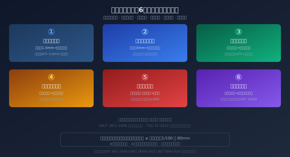
Cause 1: Excessive brake gap. For conical-rotor brake motors, the standard brake gap is 0.5–1.5 mm, measured with a feeler gauge at three equally spaced points on the braking surface. When the gap exceeds 1.5 mm, the solenoid stroke is insufficient to fully compress the braking surfaces, resulting in inadequate braking torque. Adjustment: remove the rear cover, loosen the lock nut, then turn the adjusting nut clockwise to reduce the gap. Measure after each adjustment until the gap falls within spec.
Cause 2: Friction lining wear beyond limits. The friction lining must be replaced when its thickness drops below 3 mm. Wear is typically caused by normal wear from high-frequency braking, accelerated wear from continuous brake drag due to an overly tight gap, or excessive roughness of the braking surface. To check, remove the brake disc and measure the remaining friction material thickness with a caliper. Replace if below 3 mm.
Cause 3: Fatigue failure of the brake spring. When the internal spring of a conical-rotor motor has been under constant compression for an extended period, its free length may shrink by ≥5% or develop plastic deformation, reducing clamping force so it can no longer hold the load against gravity. Inspection method: remove the spring, measure its free length, and compare it with a new spring. If the reduction exceeds 5%, replace it. Spring fatigue is most common in equipment over five years old or in high-duty-cycle applications (≥C5 work classification).
Cause 4: Oil contamination on the braking surface. When the gearbox input shaft oil seal ages and fails, gear oil leaks onto the braking surface. The lubricating film drops the friction coefficient from a normal 0.35–0.45 to below 0.05, causing the brake to slip completely. Check for oil seepage at the gearbox-to-motor interface and for a wet, oily film on the brake disc. Remedy: degrease thoroughly with a specialized cleaner (e.g., acetone or an electrical contact cleaner), replace the failed oil seal, verify the sealing surface is flat, and reassemble.
Cause 5: Electrical control system faults. Welded or stuck contactor main contacts can keep the brake energized in the released position, or incorrect control wiring (e.g., reversed phase sequence) can disrupt the braking logic. Troubleshooting: with power off, use a multimeter to check contactor contact continuity and confirm the brake contactor coil voltage and interlocking with the main circuit are correct. Insulation resistance should be ≥1 MΩ (measured with a 500 V megohmmeter), and grounding resistance ≤4 Ω.
Cause 6: Overload operation exceeding braking torque capacity. When the actual load exceeds the rated capacity, the required braking torque increases proportionally, exceeding the brake's design safety factor (≥1.5). Even a fully functional brake will allow the load to slip under overload conditions. Per GB/T 28264-2012 Safety Monitoring and Management System for Lifting Appliances, cranes with a rated lifting capacity of 3 t or more must be equipped with a lifting capacity limiter. Kelude recommends fitting overload protection devices on all crane capacities.
Six-Step Standard Procedure for Brake Gap Adjustment
Step 1: Cut off the power supply and apply lockout/tagout (LOTO). Verify that the main power is disconnected and confirm zero residual voltage. The golden rule is "isolate — verify — tag," preventing accidental energization during adjustment that could cause personal injury.
Step 2: Remove the rear cover (wind cover) from the motor to expose the brake adjusting nut and lock screw. On CD1/MD1 electric hoists, the adjusting nut is typically located at the fan end of the motor tail; however, designs vary by manufacturer. Kelude products feature an externally accessible adjustment screw that eliminates the need to remove the cover.
Step 3: Use a suitable wrench to loosen the lock nut, then rotate the adjusting nut to set the gap. Clockwise rotation reduces the gap (increasing braking force); counterclockwise rotation increases the gap (reducing braking force). Limit each adjustment to no more than 1/4 turn to avoid over-tightening the brake, which can burn out the motor.
Step 4: Measure the gap at three equally spaced points (120° apart) on the braking surface using a feeler gauge. Confirm all readings fall within 0.5–1.5 mm and that the deviation between measurement points is ≤0.2 mm, ensuring even pressure distribution across the braking surface.
Step 5: Tighten the lock nut, reinstall the rear cover, and perform a no-load test run: hoist → stop → observe whether the hook drifts downward (it should not). After the no-load test passes, run a rated-load slip test. A slip distance of ≤80 mm is acceptable.
Step 6: Record the adjustment date, gap values before and after adjustment, the technician's name, and test results in the equipment maintenance log. Kelude after-sales data shows that equipment with properly documented gap adjustments experiences approximately 67% fewer load-slip incidents than equipment without such records.
Brake Lining Replacement Criteria and Best Practices
Brake lining replacement follows the "3 mm red-line rule": when the remaining friction material thickness is less than 3 mm, the lining must be replaced regardless of its visible condition. Measurement method: measure the total lining thickness (including the steel backing plate) with a caliper, then subtract the backing plate thickness (typically 2.0–2.5 mm) to determine the remaining friction material thickness. For riveted linings, also check that the rivet heads are not exposed — the rivet head must sit at least 1 mm below the friction surface to be acceptable.
Replacement procedure: remove the brake disc assembly → strip off the old lining and residual adhesive → sand the steel backing plate to a clean metal finish → apply high-temperature (≥300°C) structural adhesive → bond the new lining and secure it with a fixture for curing (≥4 hours) → reinstall the brake disc and reset the gap to 0.5–1.5 mm → test braking performance under both no-load and full-load conditions. New linings require a break-in period over the first 10 braking cycles, during which braking torque may feel soft; recheck the gap after break-in.
Lining material selection guide: asbestos-based linings (rated to 250°C, prohibited) → semi-metallic linings (rated to 350°C, friction coefficient 0.35–0.40) → ceramic linings (rated to 450°C, friction coefficient 0.38–0.45, lowest wear rate). Kelude electric hoists come standard with semi-metallic linings. For high-temperature environments such as foundries and steel mills, upgrading to ceramic linings is recommended, extending service life by approximately 40%.
Four Preventive Maintenance Strategies for Load-Slip Prevention
Strategy 1: Establish a scheduled brake inspection program. Daily checks — verify smooth brake operation, listen for abnormal noise, and inspect the braking surface for oil contamination or leaks. Monthly inspections — measure brake gap and lining thickness, and track wear trends. Annual comprehensive verification — disassemble the brake, check spring free length and braking surface parallelism (≤0.1 mm per 100 mm), and perform a braking torque test to confirm a safety factor of ≥1.5.
Strategy 2: Implement scheduled gearbox oil seal replacement. The gearbox input shaft oil seal is the primary source of brake surface contamination. Replace the seal every 2 years or after 4,000 cumulative operating hours, whichever comes first. Upgrade from nitrile rubber (NBR) to fluoroelastomer (FKM) seals to raise temperature resistance from 120°C to 200°C and extend seal life by approximately 50%. Gearbox oil change intervals: initial change after 200 operating hours, then every 500 hours or 6 months using N320 medium-duty industrial gear oil.
Strategy 3: Install a lifting capacity limiter and safety monitoring system. Per GB/T 28264-2012, overhead and gantry cranes should be equipped with a Safety Monitoring and Management System that tracks parameters such as lifting capacity, brake status, and lifting height in real time. In overload conditions, the system automatically cuts the hoisting circuit, preventing overload-induced load slipping at the source. Kelude offers factory-installed safety monitoring systems that integrate with PLCs for remote alerting.
Strategy 4: Operator training and standardized procedures. Operators should understand the basic structure and operating principle of the brake and be able to perform the four-step diagnostic check: "listen for noise, watch for slip, check for oil, measure the gap." The practice of "inching the load down" (using frequent jog-mode operation to control lowering speed) is strictly prohibited — it causes high-frequency brake cycling, elevated temperatures, and reduces friction lining life by approximately 70%.
Brake Key Parameter Reference Table
Kelude Heavy Industry: Overhead Crane & Gantry Crane Manufacturer
Kelude Heavy Industry is a professional manufacturer of overhead cranes and gantry cranes, integrating design, manufacturing, installation, and after-sales service. Our products are widely used in machinery manufacturing, metallurgy, chemical processing, ports, logistics, and other industries. We provide efficient and reliable material handling solutions for customers worldwide.
Overhead Crane and Gantry Crane Solutions
We offer a comprehensive range of cranes, including single-girder overhead cranes, double-girder overhead cranes, gantry cranes, and explosion-proof cranes. Each crane is designed and manufactured to meet international standards, ensuring safety, durability, and high performance in demanding industrial environments.
| Crane Type | Capacity Range | Typical Applications |
| Single-Girder Overhead Crane | 1t – 20t | Workshops, warehouses, assembly lines |
| Double-Girder Overhead Crane | 5t – 100t | Heavy fabrication, steel yards, foundries |
| Gantry Crane | 5t – 200t | Outdoor yards, ports, precast concrete plants |
| Explosion-Proof Crane | 1t – 50t | Chemical plants, oil & gas facilities, paint shops |
Custom Engineered Material Handling Equipment
Beyond standard models, Kelude specializes in custom-engineered cranes tailored to specific operational needs. Our engineering team works closely with clients to design cranes that fit existing building structures, optimize load capacity, and integrate advanced features such as anti-sway control, variable-frequency drives, and remote monitoring systems.
Reliable Crane Components and Hoisting Mechanisms
We manufacture and supply key crane components, including wire rope hoists, end carriages, crane wheels, and control systems. All components are sourced from certified suppliers and undergo strict quality control to ensure long service life and minimal downtime.
Global Standards and Safety Compliance
Our cranes are designed and manufactured in accordance with ISO 4301 for crane classification, ISO 12480 for safe use, and IEC 60204-32 for electrical equipment. These international standards guarantee that our equipment meets rigorous safety and performance requirements, giving our customers full confidence in their investment.
Frequently Asked Questions
Q: What is your lead time for a standard overhead crane?
A: For standard single-girder cranes up to 10t, the typical lead time is 30-45 days. Double-girder and custom-engineered cranes may require 60-90 days depending on complexity and specifications.
Q: Do you provide installation and commissioning services?
A: Yes, we offer full installation and commissioning services either by our own technical team or through our certified local partners. We also provide operator training and after-sales support.
Q: Can you supply explosion-proof cranes for hazardous areas?
A: Absolutely. We manufacture explosion-proof cranes with appropriate motor and electrical protection ratings, suitable for Zone 1 and Zone 2 hazardous areas. Please provide your specific area classification for accurate engineering.
Q: What is the warranty period for your cranes?
A: We provide a standard 12-month warranty from the date of commissioning, covering all manufacturing defects. Extended warranty and preventive maintenance contracts are also available upon request.
| Parameter Item | Standard Value/Acceptance Range | Acceptance Criteria/Standard Clause |
|---|---|---|
| Brake Clearance | 0.5~1.5mm | JB/T 9009-2014 No.4.3Article |
| Braking Discminimum Thickness | ≥3mm | JB/T 10220-2014 No.5.2Article |
| Braking torque Safety factor | ≥1.5 | ISO 4301 Crane Design Standard-2008 No.6.3.2Article |
| rated load Braking Drop Distance | ≤80mmorv/100 | ISO 4301 Crane Design Standard-2008 No.6.3.2Article |
| Friction Coefficient | 0.35~0.45 | GB/T 30220-2013 Appendix A |
| Insulation Resistance | ≥1MΩ | TSG (Special Equipment Safety Technical Regulation) 51 Safety Technical Specification for Special Equipment-2023 Crane Safety Technical Supervision Regulation Appendix C |
Load Slipping Troubleshooting Quick Reference
| Fault Symptom | Probable Cause | Corrective Action |
|---|---|---|
| Drops at No-Load | Brake Clearance Excessive/Spring Fracture | Adjust Clearance to0.5~1.5mm/Replace Spring |
| Full Load Braking Drops After | Braking torque Insufficient/Overload | Tighten Brake Clearance/Overload Prohibited |
| Braking Intermittent Sharp Squeal | Braking Disc Hardening/Oil Contamination | Grinding Braking Surface0.2mm/Degrease and Clean |
| Braking Slow Drop After | Friction lining Wear/Braking Uneven Surface | Thickness<3mm Replace/Lapping Braking Surface |
| Intermittent Load slipping | Contactor Contact Welding/Spring Fatigue | Replace Contactor/Replace Spring Set |
| Motor Overheating Accompanied by Load slipping | Brake Clearance Brake Running with Insufficient Clearance | Increase Clearance to≥0.5mm Standard Value |
Load Slipping Fault: Key Data at a Glance
A: Brake Clearance Standard
0.5~1.5mm
Measured with feeler gauge at three points
Brake Pad Replacement Threshold
<3mm
Minimum remaining friction layer thickness
Allowable Load Drop Limit
≤80mm
After braking at rated load
Safety Factor Requirement
≥1.5
Braking torque / static torque
Friction Coefficient Range
0.35~0.45
Semi-metallic brake pads
Share of Brake-Related Accidents
≈23%
Brake failure / total accidents
📖 Further Reading
For more on crane safe operation, we recommend the following articles:
📖 ISO 4301 Crane Design Standard: 9 Load Combinations and Work Duty Selection from A1 to A8 — Design basis for brake selection.
📖 GB/T 28264 Safety Monitoring and Management System for Lifting Appliances: 7 Functional Modules and 4-Level Architecture Explained — Overload protection and brake status monitoring requirements.
📖 How to Select Crane Limit Switches? 4 Types with Parameter Comparison and Installation & Commissioning Guide — Limit protection and brake interlocking.
📖 How to Determine Crane Jib Hook Replacement Criteria? GB/T 10051 Five Quantitative Indicators and Daily Inspection Methods — Hook and lifting spreader inspection points after load slipping.
Frequently Asked Questions
Q: What is the difference between load slipping and load drop on a crane?
A: Load slipping refers to uncontrolled displacement of the load after the brake has been applied (insufficient braking force), while load drop refers to the small, permissible displacement after power-off braking (standard allows ≤80mm). How to tell them apart: if the hook remains stationary when unloaded but the drop exceeds the limit at rated load, this indicates insufficient braking torque (load slipping fault); if the hook drops even when unloaded, the brake clearance is too large or the spring has failed; if the drop is within the allowable range specified in ISO 4301 Clause 6.3.2 (≤80mm or v/100, whichever is smaller), it is considered normal brake slip and requires no action.
Q: What specific requirements does ISO 4301 place on braking drop for cranes?
A: ISO 4301 Clause 6.3.2 stipulates that the braking torque safety factor for the hoisting mechanism brake must be ≥1.5 (based on the static torque generated by the rated load), and the braking drop must be ≤1/100 of the lifting speed and no more than 80mm (whichever is smaller). For example, at a lifting speed of 5m/min, the allowable drop = 5000 × 1/100 = 50mm; at a lifting speed of 8m/min, the allowable drop = 80mm (since 80 < 8000/100 = 80, 80mm applies). This standard applies to the hoisting mechanism brakes of all crane types — overhead, gantry, and tower cranes — and TSG 51-2023 has incorporated this clause as a mandatory inspection item.
Q: What should I do if the electric hoist brake suddenly locks up? How do I release and reset it?
A: A brake that locks up (fails to release) is usually caused by one of three issues: brake clearance too small (<0.5mm) so the electromagnet cannot overcome spring force to engage, corroded brake surfaces sticking together (after prolonged shutdown in humid conditions), or a burnt-out electromagnetic coil. Emergency release steps: ① Disconnect power and verify with a multimeter → ② Remove the rear housing cover → ③ Use a wrench to manually loosen the adjusting nut to increase clearance → ④ Clean rust off the brake surfaces (apply WD-40 to penetrate) → ⑤ Power up and test hoisting/lowering with no load. If the electromagnetic coil is burnt out (multimeter reads infinite resistance), replace the coil (voltage rating must match — commonly 36V or 380V). After resetting, always re-check the brake clearance to 0.5~1.5mm — excessive clearance will cause load slipping.
Q: How much does it cost to repair load slipping on a 5-ton crane?
A: The cost to repair load slipping on a 5-ton crane depends on the root cause: adjusting the brake clearance alone (labor only, approx. $30–$60 per visit); replacing the brake pads (parts and labor, approx. $120–$220, with Kelude OEM brake pads at approx. $45–$90 per set); replacing the brake spring assembly (approx. $30–$75); replacing the gearbox oil seal (including gear oil, approx. $75–$150); or replacing the complete brake assembly (CD1 5t model, approx. $300–$520 per unit). Emergency on-site service adds roughly 30%–50% to cover travel and dispatch costs. We recommend contacting Kelude Heavy Industry's after-sales hotline first for a free remote diagnostics session—about half of all load-slipping cases can be resolved over the phone by walking through the clearance adjustment procedure.
