

How to Choose Crane Limit Switches: 4 Types Compared
ISO 4301 Crane Design Standard requires all hoisting and travel mechanisms to be equipped with limit switches as the final mechanical safeguard in crane safety protection. This article provides a detailed breakdown of selection parameters and installation & commissioning practices for four types of limit switches: heavy hammer, rotary, proximity, and photoelectric.
Limit switches (also known as travel switches) are core components in crane safety systems, and their reliability directly impacts operational safety. Under the State Administration for Market Regulation's Announcement No. 57 of 2020, overhead and gantry cranes with a lifting capacity of ≥3t fall under special equipment supervision, meaning the selection, installation, and periodic inspection of limit switches must all comply with mandatory standards. Below is a systematic analysis covering four aspects: type principles, parameter comparison, installation specifications, and commissioning methods.
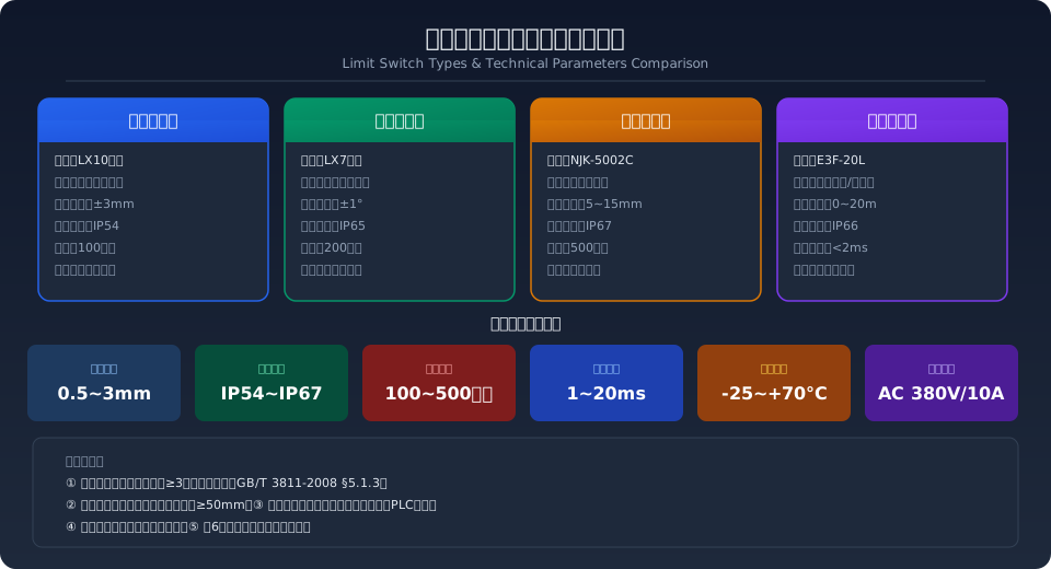
Limit Switch Types and Operating Principles
Crane limit switches fall into two broad categories based on trigger method—contact and non-contact—with four mainstream types, each suited to different operating conditions and accuracy grades.
Heavy Hammer Limit Switch (LX10 Series) — When the hook reaches its upper travel limit, it pushes against the heavy hammer, causing it to deflect and open the internal micro switch contacts, cutting off the hoisting circuit. The design is simple and cost-effective (approximately $12–$22 per unit), but repeatability is limited to ±3mm, making it suitable for standard hoisting upper-limit applications where high precision is not required.
Rotary Limit Switch (LX7 Series) — The output shaft gear of the reducer meshes with the input gear of the limit switch, converting linear travel into rotational angle to trigger the contacts. Repeatability reaches ±1°, with an IP65 protection rating. It is commonly used for dual-limit protection on crane bridge (long travel) and trolley (cross travel) mechanismsong travel) and trolley (cross travel) mechanisms, priced at roughly $30–$52 per unit.
Proximity Limit Switch (NJK Series Inductive) — Uses eddy current effects to detect the position of a metal target. It offers non-contact operation, fast response (<5ms), an adjustable sensing range of 5–15mm, an IP67 protection rating, and a service life exceeding 5 million cycles. Ideal for precise positioning in high-frequency duty applications, at approximately $9–$18 per unit.
Photoelectric Limit Switch (E3F Series Through-beam / Diffuse) — Triggers an output signal when an infrared beam is interrupted, with a maximum sensing distance of up to 20m and a response time of <2ms. It is well suited for anti-collision interlocking between two overhead cranes operating in a wide-span workshop. Note that lens cleaning is required; in dusty foundry environments, monthly wiping is recommended. Priced at roughly $22–$45 per unit.
Limit Switch Comparison: Key Parameters at a Glance
The following comparison covers six dimensions: trigger method, accuracy, protection rating, service life, cost, and application scenarios.
| Comparison Parameter | hammer-type LX10 | Rotary-type LX7 | proximity-type NJK | photoelectric-type E3F |
|---|---|---|---|---|
| actuation method | Mechanical impact (hammer deflection) | Gear transmission (angle conversion) | inductive eddy-current(non-contact) | infrared beam(non-contact) |
| repeatability | ±3mm | ±1°(approx.0.5mm) | ±0.1mm | ±2mm |
| Protection Rating (IP) | IP54 | IP65 | IP67 | IP66 |
| Mechanical service life | 100×10⁴ cycles | 200×10⁴ cycles | ≥500×10⁴ cycles | ≥300×10⁴ cycles |
| Response time | approx.20ms | approx.15ms | <5ms | <2ms |
| unit cost | 80~150CNY | 200~350CNY | 60~120CNY | 150~300CNY |
| Application Scenarios | Hoisting / Liftingupper limit switch | large Trolleydual limit switch | Precise Positioning, frequent operation | large Spananti-collision Interlock |
| maintenance points | check hammer flexibility per shift | every six months Lubrication Gear | check mounting clearance monthly | clean lenses monthly |
Installation Position & Wiring Requirements
The installation position of limit switches directly determines their protective effectiveness. Clear standard requirements govern the mounting spacing and wiring methods for each type of limit device.
Hoisting Upper Limit Switch Installation — The heavy hammer limit switch should be mounted on the hoist or trolley frame, with the hammer chain/wire rope suspended above the extreme position of the hook block. When triggered, the hook block sheave must maintain at least 3 wraps of wire rope remaining on the drum (refer to ISO 4301, Section 5.1.3). The hammer travel distance should be ≥150mm to ensure reliable triggering and reset.
Crane Bridge & Trolley Travel Limit Switch Installation — Rotary or proximity-type limit switches are installed at the crane end carriage or trolley frame ends, with the matching trip dogs (bumpers) fixed to the buffer stops at the rail ends. When triggered, the distance between the limit switch and the rail-end buffer stop should be ≥50mm (leaving compression allowance for the buffer). The trip dog height should cover the full travel of the limit switch sensing face.
Wiring Requirements — Limit switches must be wired directly in series with the main contactor or relay control coil circuit of the corresponding mechanism (safety circuit). They must not be connected only to a PLC input for software-based judgment. The normally closed (NC) contacts of the limit switch remain closed under normal conditions and open when triggered, implementing the fail-safe "de-energize to stop" principle. The minimum spacing between signal cables and power cables should be ≥200mm, with cables routed through metal conduit or metal hose for protection and grounded at both ends.
Commissioning Procedure & Acceptance Criteria
After installation, each limit switch must be individually commissioned following the four-step procedure below, with all data recorded:
Step 1: Static Trigger Test — Manually operate the mechanism at low speed to the limit position, then use a feeler gauge or Laser Distance Sensor to measure the deviation between the actual trigger position and the theoretical position. The trigger deviation for the hoisting upper limit should be ≤5mm, and for crane bridge/trolley travel limits ≤10mm. Record the trigger coordinates of each limit switch.
Step 2: Dynamic Repeatability Test — Run the mechanism at rated speed 5 times, measuring the consistency of the actual stop position each time the limit position is reached. The position deviation for repeated triggering in the same direction should be ≤3mm (or ≤1°). If the deviation exceeds the tolerance, check for loose trip dogs or deformed limit switch brackets.
Step 3: Safety Circuit Interlock Verification — With the limit switch in the triggered state, verify that the corresponding hoisting or travel mechanism cannot continue moving in the hazardous direction (it may only move in the reverse direction). Use a multimeter to confirm the control circuit is de-energized and that the limit switch contacts have indeed opened the contactor coil circuit.
Step 4: Acceptance Record Archiving — Record the model, installation position coordinates, trigger deviation, repeatability, test date, and tester signature for each limit switch in the Crane Safety Device Commissioning Record Sheet. This documentation is retained as Factory Acceptance Test (FAT) records required under TSG 51-2023 Crane Safety Technical Supervision Regulation.
Key Specification Quick Reference
Applicable Standards & Inspection Requirements
The design, selection, and inspection of crane limit switches are governed by multiple national standards and safety technical regulations. The primary references are as follows:
ISO 4301 Crane Design Standard (formerly ISO 4301) — Section 5.1.3 mandates that hoisting mechanisms must be equipped with an upper final limit switch, and Section 5.2.4 requires travel mechanisms to be fitted with travel limit switches. The limit device must automatically cut off the power source, and after reset, the mechanism may only move in the safe direction. This is the fundamental design basis for limit switch selection.
ISO 12480 Safety Code for Lifting Appliances (formerly ISO 12480) — Section 9.2 requires that all limit switches remain functionally effective during service, with a no-load functional test to be performed before each work shift. Section 12.3.2 specifies the inspection intervals for limit switches: every 12 months in normal industrial environments, every 6 months in high-temperature/high-humidity/corrosive environments, and every 6 months for continuous-duty cranes classified at A7~A8.
Overload Protection Devices for Lifting Appliances (formerly GB/T 12602-2020) — Although primarily addressing overload limiters, Section 4.2.4 sets a comprehensive error requirement of ≤±5%, which equally applies to intelligent limit systems with load detection functionality. For systems using PLC-based limit signal processing, the signal acquisition cycle should be ≤20ms to ensure real-time response.
In practical engineering applications, limit switch selection should also account for work duty classification, ambient temperature (-25~+70°C), dust concentration, and vibration intensity. For Metallurgical Crane applications in high-temperature environments, the temperature resistance rating of limit switches should be no lower than Class H (180°C), with cables using high-temperature-resistant silicone rubber sheathing.
Related Reading: ISO 4301 Crane Design Standard · ISO 12480 Safety Code for Lifting Appliances · GB/T 12602-2020 Overload Protection Devices for Lifting Appliances · Design of Forward/Reverse Contactor Interlock Circuits for Cranes
Frequently Asked Questions
Q: What are the specific installation requirements for the upper hoist limit switch under ISO 4301?
A: The standard explicitly requires that the hoisting mechanism be equipped with an upper final limit switch. When triggered, the hook block sheave must maintain at least 3 full wraps of wire rope remaining on the drum. Once the limit switch is activated, the hoisting mechanism may only operate in the lowering direction—hoisting is prohibited. For double-reel drum configurations, the difference in remaining wraps between the two sides must not exceed 1 wrap. This requirement applies to all electric hoists and hoist winch mechanisms on bridge cranes, gantry cranes, and cantilever cranes, and is a mandatory inspection item under the TSG 51-2023 Type Test.
Q: How do I choose between a weight limit switch and a rotary limit switch? What are the pros, cons, and applicable tonnage ranges?
A: The weight-type (LX10 series) is simple in construction and low in cost (approx. $12–$22), but its repeatability is only ±3 mm, and the weight chain tends to sway and cause nuisance trips in windy or high-temperature environments. It suits hoist upper-limit applications on light-duty hoists up to 5 t. The rotary type (LX7 series) converts linear travel into angular displacement via a gear train, offering ±1° repeatability and IP65 protection. It is suitable for both travel and hoist limit functions on bridge cranes rated 16 t and above, but costs more (approx. $30–$52) and requires coupling to the gearbox output shaft during installation. For hoisting mechanisms with frequent duty cycles (A6 and above), a redundant rotary-plus-proximity configuration is recommended.
Q: How do I troubleshoot a proximity limit switch that fails to trigger or triggers falsely? What are the 3 most common causes and fixes?
A: First, check the mounting gap—if it exceeds 80% of the rated sensing distance, use a feeler gauge to reset it to 50–70% of the rated value. Second, verify the target material: inductive proximity switches only respond to ferromagnetic metals. Stainless steel or aluminum targets will drastically reduce sensing range or prevent triggering altogether—replace them with Q235 steel targets. Third, inspect cable routing: if the proximity switch signal cable runs less than 200 mm from a VFD output cable, high-frequency harmonics can couple into the signal line and cause false triggers. Route the signal cable through metal conduit with single-point grounding. Recommended troubleshooting sequence: check gap first, then target material, then wiring.
Q: How many years does a limit switch typically last? Under what conditions must it be replaced early? What are the replacement criteria?
A: Mechanical limit switches (weight-type and rotary-type) have a design life of 1 to 2 million operating cycles—roughly 5 to 8 years under normal duty on a A5 crane. Proximity and photoelectric types, having no mechanical wear, last up to 5 million and 3 million cycles respectively—about 8 to 12 years. Immediate replacement is required if any of the following occurs: ① contact resistance exceeds 50 mΩ (measured with a milliohm meter); ② the housing shows cracks or the protective seal fails (hardened or detached sealant); ③ repeatability exceeds twice the rated value (e.g., actual deviation greater than ±6 mm on a weight-type switch); ④ actuating force exceeds 1.5 times the rated value (measured with a push-pull tension meter). In corrosive environments such as metallurgical or chemical plants, the replacement interval should be shortened by 50%.
