

Crane Contactor Interlock Circuit Design for Forward-Reverse Control
The forward/reverse contactor interlock circuit for cranes is designed in accordance with IEC 60204-32 and IEC 60947-4-1, incorporating dual protection through electrical interlocking (cross-wired NC auxiliary contacts) and mechanical interlocking (linked pushbutton mechanism). This ensures KM1 and KM2 can never energize simultaneously, fundamentally preventing phase-to-phase short circuits.
In the hoisting, long travel, and trolley travel mechanisms of a crane, forward/reverse motor control is the most fundamental electrical function. However, if contactors KM1 and KM2 were to close at the same time, phases L1 and L3 of the three-phase supply would short-circuit directly through the main contacts—one of the most dangerous faults in a crane electrical cabinet. At best, it destroys the contactors and motor; at worst, it causes an electrical fire. The quality of the interlock circuit design therefore directly determines the safety level of the crane's electrical system.
This article examines the dual-protection principle of electrical and mechanical interlocking, using a practical wiring scheme with CJX2-series AC contactors. It covers component selection, wiring steps, commissioning procedures, and common fault-diagnosis workflows for crane forward/reverse control circuits.
Why Contactor Interlocks Are Essential for Crane Safety
The hoisting mechanism's up/down motion, the long-travel mechanism's left/right movement, and the trolley travel mechanism's forward/reverse travel are all achieved by two AC contactors, KM1 and KM2, controlling motor rotation in opposite directions. If the main contacts of both contactors close simultaneously, phases L1 and L3 are short-circuited directly in the power circuit—short-circuit currents can reach thousands of amperes, instantly welding contactor tips, melting wire insulation, and in severe cases triggering an electrical fire.
IEC 60204-32 (Safety of machinery—Electrical equipment of machines—Part 32: Requirements for hoisting machines) explicitly requires electrical interlocking between forward and reverse contactors in lifting appliances to prevent simultaneous energization caused by contactor welding or control-circuit faults. TSG 51-2023 Crane Safety Technical Supervision Regulation further stipulates that control circuits related to safety functions must adopt redundancy design and fail-safe principles.
Dual Interlock Circuit Design: How It Works
The crane forward/reverse control circuit employs both electrical and mechanical interlocking as independent, redundant protection layers. If one layer fails, the other still prevents KM1 and KM2 from closing simultaneously.
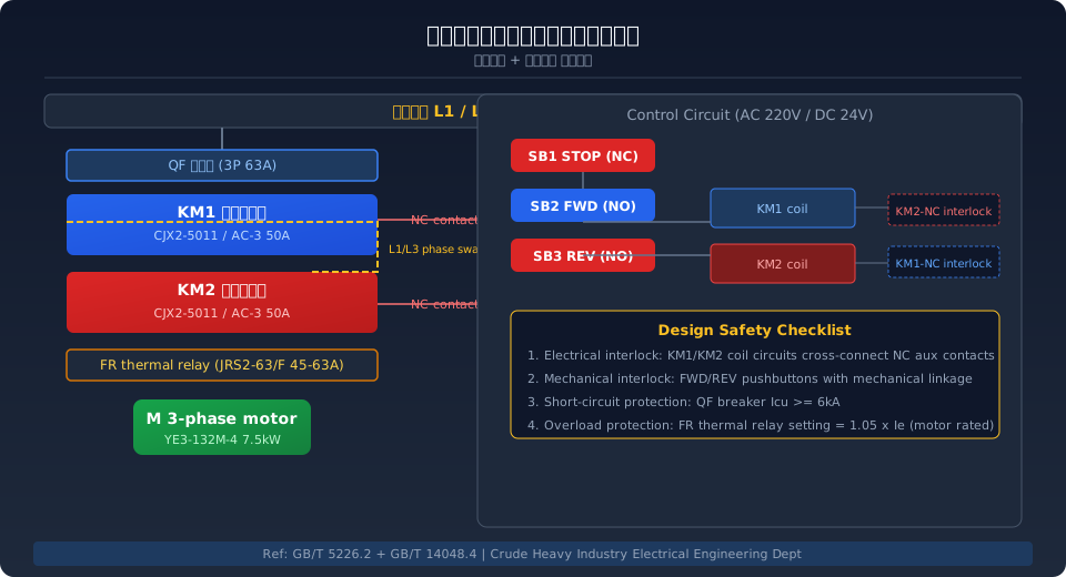
Electrical interlock—A normally closed (NC) auxiliary contact from KM1 is wired in series with the KM2 coil circuit, and an NC auxiliary contact from KM2 is wired in series with the KM1 coil circuit. When KM1 energizes and closes, its NC contact opens, physically cutting off the supply to the KM2 coil—and vice versa. This cross-wired arrangement guarantees at the circuit-topology level that KM1 and KM2 cannot be energized at the same time.
Mechanical interlock—The forward pushbutton SB2 and reverse pushbutton SB3 are a mechanically linked dual-button assembly (e.g., LAY7-11BN/3). The moving contacts of both buttons are interlocked through a lever mechanism: pressing SB2 forces the moving contact of SB3 to open, and vice versa. Even if the operator presses both buttons simultaneously, only the button that makes contact first completes the circuit; the other is mechanically locked in the open position.
Component Selection and Key Parameters
The reliability of a contactor interlock circuit depends not only on the design principle but equally on correct component selection. Below are the selection criteria and recommended models for key components in both the power circuit and the control circuit.
Contactor rated current selection: Under AC-3 duty, the contactor rated current Ie must be at least 1.25 times the motor rated current In. For example, with a YE3-132M-4 7.5kW motor (In = 15.2A), a CJX2-5011 (50A) contactor provides ample margin. The F4-22 auxiliary contact block supplies 2 NO + 2 NC contacts, with one NC contact from each block used for electrical interlocking. The thermal overload relay FR should be set to 1.05 times the motor rated current, i.e., 1.05 × 15.2A = 16.0A.
Wiring and Commissioning Procedure
Wire and commission the contactor interlock circuit in the following five steps. De-energize the circuit and verify each step with a multimeter.
Step 1: Power circuit wiring—From circuit breaker QF, run L1/L2/L3 to the top terminals of KM1 (1/L1, 3/L2, 5/L3). Connect the bottom terminals of KM1 (2/T1, 4/T2, 6/T3) to the top terminals of KM2, but cross-swap the L1 and L3 phases: KM1's 2/T1 (L1 phase) goes to KM2's 5/L3 (L3 phase), and KM1's 6/T3 (L3 phase) goes to KM2's 1/L1 (L1 phase). The L2 phase connects straight through. From the bottom of KM2, run to the top of thermal overload relay FR, then from FR's bottom terminals run U/V/W to the motor.
Step 2: Control circuit wiring—Take the control power feed from phase L1 of circuit breaker QF. Wire in series the stop pushbutton SB1 (NC) and the forward pushbutton SB2 (NO). From there, split into two branches: the forward branch goes through KM2's NC auxiliary contact (electrical interlock) to the A1 terminal of the KM1 coil; the reverse branch goes through KM1's NC auxiliary contact to the A1 terminal of the KM2 coil. Tie the A2 terminals of both coils together and return to the control neutral N.
Step 3: Self-Locking Contactor Wiring — Wire the KM1 coil in parallel with KM1's NO auxiliary contact (self-locking contact), and do the same for KM2. This way, once the start button is released, the contactor maintains coil power through its own NO contact, achieving self-holding functionality.
Step 4: Static Testing Before Power-Up — Disconnect the main circuit breaker QF, then use a multimeter in resistance mode to check the control circuit point by point: when SB2 is pressed, the KM1 coil should show continuity (resistance approximately 50–80 Ω), while the KM2 coil should read open circuit (NC interlock contact is open); pressing SB3 should produce the opposite results. When both SB2 and SB3 are pressed simultaneously, the mechanical interlock should prevent both circuits from energizing at the same time.
Step 5: Dynamic Commissioning and Load Testing — First disconnect the motor wiring (leave U/V/W terminals at the FR output floating), close circuit breaker QF, then press SB2, SB1, SB3, and SB1 in sequence. Using a multimeter in AC voltage mode at the FR output, verify: pressing SB2 delivers normal three-phase voltage at U/V/W with correct phase sequence; pressing SB3 also delivers normal three-phase voltage but with L1/L3 swapped. Check that the contactors pull in with a crisp sound and no chattering, and that coil temperature rise remains within normal limits. Finally, reconnect the motor and run it for 5 minutes under both no-load and rated-load conditions to confirm correct rotation direction and smooth operation.
Interlock Scheme Comparison: 6 Common Approaches
Interlock solutions vary in reliability, cost, and suitability across different applications. The table below compares six common approaches across four key dimensions.
| Interlock Solution | Reliability Assessment | Additional Cost | Application Scenarios |
|---|---|---|---|
| electrical interlock(NCContact) | High——Contact Failure Rate Approx.0.01% | Zero Additional Cost | Small to Mediumcrane Standard Configuration |
| mechanical interlock Push Button | Relatively High——Machinery Service Life1,000,000 Cycles | Push Button Cost Increase Approx.30RMB | Allcrane Control Console Standard Configuration |
| PLCSoftware Interlock | Medium——Dependent on Program Scan Cycle | Requires PLCModule Contact Failure Rate Approx.500RMB | Automation/Smart Crane |
| Contactor Mechanical Interlock Module | Highest——Physical Interlock | Push Button Cost Increase Approx.50RMB/Control Console | Large Poweror Safety-Critical Applications |
| Time Delay Relay Transition Interlock | Medium——Requires Precise Setting0.1~0.3s | Push Button Cost Increase Approx.80RMB | Frequent Forward/Reverse/Inching / Jog Mode Operating Condition |
| Kruud Recommended Solution | Electrical+Machinery+PLCThree-Tier | Overall Cost Controllable | Intelligentoverhead crane Standard Factory Configuration |
Common Fault Analysis and Troubleshooting
Crane forward/reverse control circuits can develop faults over extended service, including interlock failure, contactors failing to pick up, or unexpected tripping. Below are the three most common fault types and their troubleshooting procedures.
Fault 1: Forward rotation works but reverse fails to start — First, check whether the NO contact of reverse pushbutton SB3 conducts (measure with a multimeter in continuity mode), then check whether the NC auxiliary contact of KM1 has degraded due to prolonged use. With the multimeter set to resistance mode, the NC contact of KM1 (typically terminals 61-62) should read near 0 Ω when KM1 is de-energized. If resistance exceeds 10 Ω, replace the auxiliary contact block. Finally, verify the KM2 coil resistance is within the normal range (50–80 Ω); if the coil is open, replace the contactor.
Fault 2: Contactor picks up then immediately drops out (chattering) — Poor contact on the sealing contact is the most common cause. At the instant KM1 picks up, the KM1-NO auxiliary contact (typically terminals 53-54) wired in parallel across SB2 must close reliably to maintain coil supply. If this contact is oxidized or the spring has fatigued, causing excessive contact resistance, the coil loses power when SB2 is released and the contactor drops out; when SB2 is pressed again, the circuit re-energizes, producing a rapid pick-up/drop-out chatter. The fix is to clean or replace the auxiliary contact. In an emergency, temporarily short the sealing contact wiring to keep the circuit running.
Fault 3: Circuit breaker trips immediately upon closing — Phase-to-phase short circuit in the power circuit. First, check whether the main contacts of KM1 and KM2 close simultaneously (de-energize the control power and manually press the contactor armatures to observe). If both contactors' main contacts are closed, the interlock circuit has completely failed. In this case, de-energize immediately, replace the interlock contacts in the control circuit, and verify the phase-reversal wiring on L1/L3 in the power circuit — incorrect phase-reversal wiring (L1/L3 not crossed) will leave motor direction unchanged but will not cause a short circuit; however, if KM1/KM2 are wired to the same phases and both pick up due to interlock failure, a direct short circuit results.
Related Reading
More on crane electrical safety and standard interpretation:
① IEC 60204-32: Safety of Machinery — Electrical Equipment of Machines — Design, selection, and installation requirements for crane electrical equipment;
② TSG 51-2023 Crane Safety Technical Supervision Regulation — Redundancy design and fail-safe principles for safety control circuits;
③ ISO 4301: Cranes — Classification — Design calculations and safety factors for hoisting and travel mechanisms.
④ GB/T 28264 Safety Monitoring and Management System — Parameter Configuration and Acceptance — Monitoring parameter setup and acceptance criteria for crane electrical control systems;
⑤ Crane Electrical Control System Selection and Configuration Guide — A full-component selection guide from contactors to PLC.
Frequently Asked Questions
Q: Which is more reliable for crane contactors — electrical interlock or mechanical interlock? Can only one be used?
A: Both interlock mechanisms have their advantages: electrical interlock provides circuit-level protection through cross-wired NC auxiliary contacts, with reliability depending on the auxiliary contact's mechanical life (typically 1 million operations); mechanical interlock provides physical-level protection through pushbutton linkage mechanisms and is unaffected by circuit faults. Per TSG 51-2023 requirements, control circuits involving safety functions must adopt redundancy design, so both must be configured together — neither can be omitted. For PLC-controlled smart cranes, a third layer of software interlock is also required (cross-programming the NC contacts of forward output Q0.0 and reverse output Q0.1).
Q: How do I determine whether a contactor NC auxiliary contact is damaged? What is the replacement interval?
A: To check an NC auxiliary contact, measure it with a multimeter in resistance mode while the contactor is de-energized — it should read near 0 Ω (closed circuit). If resistance exceeds 10 Ω or the reading is intermittent, replacement is required. With the contactor energized, the NC contact should read open circuit (infinite resistance). We recommend checking auxiliary contact resistance every six months and replacing the auxiliary contact block (model F4-22) every 2 years or after 500,000 operations, whichever comes first. For cranes operating in high-temperature, dusty environments such as metallurgy or casting, shorten the inspection interval to 3 months and the replacement interval to 1 year.
Q: How does the forward/reverse contactor interlock circuit for a multi-speed motor (two-speed/three-speed) differ from that of a single-speed motor?
A: Multi-speed motor forward/reverse control requires multiple contactor groups to switch windings between different pole configurations. Taking a two-speed motor (e.g., YD series 4/16-pole) as an example: at low speed, KM3/KM4 handle the delta winding connection; at high speed, KM5 handles the double-star connection. Beyond the standard forward/reverse interlock (KM1/KM2), the interlock circuit must also include high/low-speed interlock (between KM3+KM4 and KM5), star-delta transition interlock, and a global interlock across all contactors. Intermediate relays (KA) are typically used for logic combination, or a PLC is used directly to simplify wiring.
Q: What causes frequent contactor coil burnout in cranes, and how can it be prevented?
A: There are three common causes of contactor coil burnout. First, excessive fluctuation in control power supply voltage — for a coil rated at AC 220V, sustained voltage below 187V (-15%) results in insufficient pick-up force, contact chatter and arcing, increased coil current, and thermal burnout; voltage above 253V (+15%) causes core magnetic saturation and coil overheating. Second, oil contamination or corrosion on the contactor pole faces increases magnetic circuit reluctance, causing prolonged coil overcurrent. Third, excessively high switching frequency (over 600 operations per hour) prevents the coil from dissipating heat. Preventive actions include: installing a stabilized power supply on the control circuit, regularly cleaning the contactor yoke faces, and using electronic contactors or solid state relays (SSRs) in high-frequency switching applications.
Kelude Heavy Industry Electrical Engineering Division — Specializing in the design, manufacturing, and commissioning of crane electrical control systems. From single-girder to double-girder cranes, from conventional control to PLC-based variable-frequency speed control, Kelude Heavy Industry equips every crane with dual interlock as standard to ensure electrical system safety and reliability. Electrical technical consultation: 400-086-9590.
