

How to Choose Crane Pulley Block Ratio: Formula & Selection Chart
The pulley ratio (m) is a core design parameter for a crane's hoisting mechanism. It is defined as the ratio of the number of wire rope falls (N) to the number of rope ends wound onto the drum (m = N/2 for a double-fall pulley block). This ratio directly determines the line pull, wire rope diameter, drum dimensions, and lifting speed. Selecting the correct ratio can reduce wire rope costs by 15%–30% while still meeting the safety factor requirements of ISO 4301 Crane Design Standard.
The pulley ratio is one of the most fundamental parameters in the design of hoisting mechanisms for bridge cranes and gantry cranes. It governs both the load distribution across the hoisting mechanism and the resulting wire rope diameter and drum size. If the ratio is too low, the wire rope becomes overly thick and the drum excessively long, driving up manufacturing costs. If the ratio is too high, lifting speed drops proportionally, hampering productivity. This article starts with the fundamentals, then walks through the calculation methods, selection criteria, and real-world engineering examples for pulley ratios.
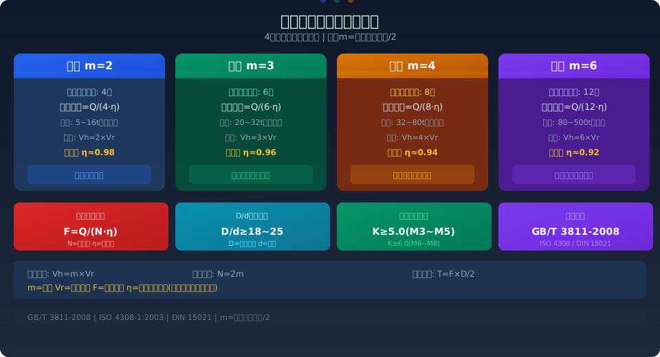
Pulley Ratio Fundamentals and Mechanical Principles
In a double-reel pulley block — the most common configuration for overhead cranes — the ratio m is defined as the total number of wire rope falls divided by the number of rope ends wound onto the drum. In a typical four-rope arrangement, for example, four rope falls carry the load while two ends wind onto the drum, giving m = 4/2 = 2. In this case, each rope carries approximately Q/(4 × η), where η is the overall efficiency of the pulley block.
The pulley ratio is essentially a load-distribution mechanism: the higher the ratio, the lower the tension in each individual rope, and the smaller the required wire rope diameter. However, lifting speed decreases proportionally (Vh = m × Vr, where Vr is the drum linear speed). Per ISO 4301 Crane Design Standard, the minimum safety factor K for wire rope depends on the crane service rating: for classifications M3 to M5, K must be no less than 5.0; for M6 to M8, K must be no less than 6.0. The ratio must strike the optimal balance between load distribution and speed.
The overall efficiency η of the pulley block is directly tied to friction losses in each sheave. Plain bearing sheaves typically offer efficiencies of 0.94–0.96 per sheave, while rolling bearing sheaves reach 0.97–0.99 per sheave. For an m = 4 (8-fall) configuration with rolling bearing sheaves, the overall efficiency is approximately 0.96, meaning roughly 4% of the power is lost to sheave friction. In engineering calculations, sheave efficiency must be factored into the line pull formula: F = Q/(N × η), not simply Q/N.
Pulley Ratio Calculation Formulas and Key Parameters
The core formulas for pulley ratio calculations are as follows (for double-reel pulley blocks with double drums):
Ratio definition: m = N / n, where N is the total number of wire rope falls and n is the number of rope ends wound onto the drum. For a standard double-reel, double-drum configuration, n = 2, so m = N/2. Common values are m = 2, 3, 4, 6, and 8.
Maximum static line pull: F_max = (Q + Q0) / (N × ηtotal), where Q is the rated lifting capacity (including the lifting spreader's dead weight), Q0 is the hook block weight, N = 2m, and ηtotal is the overall pulley block efficiency. For example, with Q = 20t, m = 3 (N = 6), and ηtotal = 0.96, F_max = (20,000 + 500) / (6 × 0.96) ≈ 3,560 kg.
Minimum wire rope diameter: d_min = C × √(F_max), where C is the wire rope selection coefficient (dependent on the rope's tensile strength and the mechanism's work duty). For 1770 MPa wire rope at M5 classification, C is approximately 0.085–0.095. In the example above, d_min ≈ 0.09 × √(3,560) ≈ 5.4 mm, typically rounded up to 6 mm or 8 mm in practice.
Lifting speed: Vh = Vr × m, where Vr is the drum surface speed. With a fixed motor speed and reduction ratio, each increment of m increases the lifting speed by Vr, while reducing the line pull by approximately Q/(2 × ηtotal).
Pulley Ratio Selection Reference Table
The table below provides recommended pulley ratios by lifting capacity range, factoring in wire rope diameter economy, drum length constraints, and lifting speed requirements:
| Lifting Capacity(t) | Work Duty / Classification | Recommended Pulley Ratiom | Number of Falls N | Typical Rope Diameter(mm) | Pulley Efficiencyeta |
|---|---|---|---|---|---|
| 5~10t | M3~M4 | 2 | 4 | 8~12mm | 0.98 |
| 10~20t | M4~M5 | 2~3 | 4~6 | 10~14mm | 0.96~0.98 |
| 20~32t | M5~M6 | 3~4 | 6~8 | 12~16mm | 0.94~0.96 |
| 32~50t | M5~M6 | 4 | 8 | 14~18mm | 0.94 |
| 50~80t | M6~M7 | 4~6 | 8~12 | 16~22mm | 0.92~0.94 |
| 80~200t | M7~M8 | 6 | 12 | 18~28mm | 0.92 |
Note: The table above assumes rolling bearings for pulleys (efficiency 0.98–0.99 per pulley) and 1770 MPa wire rope. For pulleys with plain bearings, the rope pull increases by approximately 5%–8%, and the wire rope diameter should be increased by one size accordingly.
How Pulley Ratio Affects Wire Rope and Drum Sizing
The pulley block ratio directly determines two key parameters that drive hoisting mechanism costs: wire rope diameter and drum length. Using a 20t lifting capacity with a 12m lifting height as an example, the following compares engineering parameters across different pulley ratios:
| Comparison Parameter | m=2(N=4) | m=3(N=6) | m=4(N=8) |
|---|---|---|---|
| Single Line Pull F(kg) | Approx.5220 | Approx.3480 | Approx.2610 |
| wire rope diameter(mm) | 14~16 | 11~13 | 10~11 |
| drum diameter(mm) | Approx.320(D/d=20) | Approx.260 | Approx.220 |
| Drum Length(mm) | Approx.1800 | Approx.1200 | Approx.900 |
| Lifting Speed Comparison | 1.0(Baseline) | 1.5xBaseline | 2.0xBaseline |
| Rope Cost(CNY/Unit) | Approx.2800 | Approx.2100 | Approx.1800 |
The table above shows that increasing the pulley ratio from 2 to 4 reduces the wire rope diameter by roughly 30%, shortens the drum length by about 50%, and cuts wire rope cost by approximately 35%. The trade-off, however, is that the lifting speed doubles (requiring a higher-speed motor or a lower reduction ratio), and the added sheaves bring the overall pulley block efficiency down from 0.98 to about 0.94. In essence, selecting the pulley ratio is a three-way trade-off among cost, efficiency, and speed.
Engineering Selection Examples
The following three typical engineering cases walk through the complete pulley ratio selection and calculation process.
Case 1: LD Type 5t Single-Girder Bridge Crane — Lifting capacity Q=5t, lifting height H=9m, work duty M4 (A4), lifting speed Vh=8m/min. Selected pulley ratio m=2 (N=4). Pulley block efficiency etatotal=0.98, single-rope tension F=(5000+300)/(4*0.98)≈1352kg. Using 6x19W+FC-1770 wire rope with diameter d=8mm (minimum breaking force 41.3kN), the safety factor K=41.3*1000/(1352*9.81)≈3.1 — below the M4 requirement of K≥5.0. Switching to a 10mm diameter (breaking force 63.5kN) gives K=63.5*1000/(1352*9.81)≈4.8, still close to but under the 5.0 threshold. The final selection is d=11mm (breaking force 77.8kN), yielding K≈5.9, which meets the K≥5.0 requirement.
Case 2: QD Type 32t Double-Girder Bridge Crane — Lifting capacity Q=32t, lifting height H=16m, work duty M6 (A6), lifting speed Vh=5m/min. Selected pulley ratio m=4 (N=8). Pulley block efficiency etatotal=0.94, single-rope tension F=(32000+1200)/(8*0.94)≈4415kg. Using 6x36WS+IWRC-1770 wire rope with diameter d=14mm (breaking force 124kN), the safety factor K=124*1000/(4415*9.81)≈2.86 — far below the M6 requirement of K≥6.0. Upgrading to d=18mm (breaking force 213kN) gives K=213*1000/(4415*9.81)≈4.92, still insufficient. Moving to d=20mm (breaking force 265kN) yields K=265*1000/(4415*9.81)≈6.12, meeting the K≥6.0 requirement. This example demonstrates that even with a pulley ratio of m=4, heavy-duty cranes still require a substantially larger wire rope diameter to satisfy the stringent safety factor requirements.
Case 3: Gantry Crane 75t Main Hoist — Lifting capacity Q=75t, lifting height H=20m, work duty M7 (A7), lifting speed Vh=3m/min. Selected pulley ratio m=6 (N=12). Pulley block efficiency etatotal=0.92, single-rope tension F=(75000+2500)/(12*0.92)≈7020kg. Using 6x36WS+IWRC-1960 wire rope with diameter d=22mm (breaking force 334kN), the safety factor K=334*1000/(7020*9.81)≈4.85 — below the M7 requirement of K≥6.0. Upgrading to d=26mm (breaking force 470kN) gives K=470*1000/(7020*9.81)≈6.82, meeting the K≥6.0 requirement. This case shows that for extra-heavy-duty cranes above 75t, even a pulley ratio of 6 still calls for a wire rope of 26mm or larger to ensure safety.
Applicable Standards and Further Reading
Pulley ratio design and calculation involve multiple national and international standards. The following core references are recommended:
ISO 4301 Crane Design Standard — Section 5.3 "Hoisting Mechanism" specifies the wire rope safety factor K, the ratio of sheave diameter to wire rope diameter (D/d), and drum diameter calculations. This is the most fundamental design basis for pulley ratio selection.
ISO 4308 Cranes — Selection of wire ropes — Defines the selection coefficient C for wire ropes under different work duties and the influence factor of pulley block ratio on rope fatigue life.
GB/T 22416 Pulley Blocks for Cranes — Specifies the types, basic parameters, technical requirements, and test methods for pulley blocks, serving as the direct basis for pulley block manufacturing and selection.
DIN 15021 Design Principles for Crane Drums and Sheaves — Provides recommended ratios of drum diameter D to wire rope diameter d (D/d=18~25), as well as the fit tolerances between the sheave rope groove radius and the wire rope diameter.
Frequently Asked Questions
Q: What is the specific impact of pulley ratios m=4 and m=6 on wire rope fatigue life?
A: At a pulley ratio of m=6, the tension on each wire rope is approximately 67% of that at m=4, resulting in lower bending stress and typically 30%~50% longer fatigue life. However, the increased number of sheaves (from 8 to 12) also raises the number of bending cycles the rope undergoes. ISO 4308-1:2003 recommends preferring a larger pulley ratio to extend wire rope life, provided the D/d ratio is no less than 20 — but the combined effects of reduced pulley block efficiency and lower lifting speed must also be evaluated.
Q: Why does ISO 4301 require different safety factors for different work duties?
A: The higher the work duty classification (M6~M8), the more frequently the crane operates and the heavier the loads it handles, which means the wire rope experiences more alternating stress cycles. For M3~M4 duties, a safety factor of K≥5.0 is sufficient for a fatigue life of 45,000 bending cycles, while M7~M8 duties require K≥6.0 to maintain safety after 1,000,000 cycles. The higher safety factor is achieved by increasing the wire rope diameter or by increasing the pulley ratio (which reduces the tension per rope).
Q: What is the impact of choosing a D/d ratio of 18 versus 25 on selection?
A: The D/d ratio directly affects the bending fatigue life of the wire rope. Increasing D/d from 18 to 25 improves bending fatigue life by approximately 2 to 3 times. However, a larger D means larger sheaves and drums, which adds weight to the hoisting mechanism. For light-duty applications (M3~M4), a D/d of no less than 18 is adequate; for heavy and extra-heavy duties (M6~M8), a D/d of 22~25 is recommended; and for extreme conditions such as metallurgical casting, D/d should be no less than 28.
Q: Can an existing crane be retrofitted with a larger pulley ratio to reduce wire rope consumption costs?
A: Theoretically yes, but it involves a synchronized retrofit of the pulley block, drum, motor, and reducer — a significant engineering effort with considerable cost. Taking a 32t QD Type crane as an example, changing from m=4 to m=6 requires adding 2 movable sheaves and 1 fixed sheave, shortening the effective drum length, and simultaneously adjusting the motor power and reduction ratio. In practice, it is usually more economical to optimize the pulley ratio during the design phase of a new crane. For existing equipment, a full technical and economic feasibility study is recommended before proceeding with a retrofit.
Kelude Heavy Industry strictly follows the requirements of ISO 4301 Crane Design Standard and ISO 4308 Cranes — Selection of wire ropes in the Design & Manufacturing of bridge and gantry cranes. We tailor the optimal pulley block ratio configuration based on lifting capacity and work duty classification, ensuring the wire rope safety factor meets standards while balancing cost efficiency and operational productivity. For technical consultation on pulley ratio selection, contact the Kelude engineering team.
