Non-Standard Crane Travel: Curved Rail & Steep Slope Design
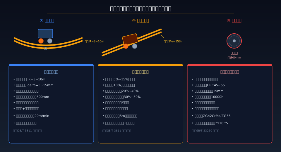
Special operating conditions for non-standard crane travel mechanisms: curved rail minimum radius R=3–10 m, rail gauge widening 5–15 mm; grades up to 5%–15% with drive power increased 20%–40%; heavy-duty wheel diameters up to 800 mm with tread hardness HRC45–55. Kelude Heavy Industry has accumulated design experience and engineering solutions for these three core challenges across non-standard projects involving circular rails, sloped transitions, and ultra-large tonnage cranes.
One of the biggest differences between non-standard and standard cranes is that the travel mechanism must adapt to a wide range of special rail conditions and operating environments. Curved rail travel, steep grade operation, and heavy-duty wheel design are the three most common technical hurdles — and the ones most often underestimated during the design phase. Curved rail involves the bending radius, rail gauge widening, and clearance between the wheel flange and rail; steep grades require climbing capability verification, braking safety, and anti-slip measures; heavy-duty wheels involve diameter matching, tread hardness, bearing life, and wheel load distribution. This article breaks down each of these three design challenges.
Curved Rail Travel Mechanism Design
Curved rail travel is one of the most common special rail configurations for non-standard cranes, typically found in circular factory buildings, round storage silos, and assembly line transfer stations. The core design parameter is the minimum bending radius R, which depends on crane span, travel speed, and wheel base. Practical engineering values range from R=3–10 m. The smaller the radius, the harder the turn and the greater the lateral forces between the wheels and the rail. In the curved section, the rail gauge must be widened by 5–15 mm (with the inner rail shifted toward the circle center). The widening amount is calculated as delta=L²/(8R), where L is the wheel base and R is the bending radius.
Curved rail travel design also involves controlling the clearance between the wheel flange and the rail. Standard clearance on straight track is 8–12 mm, but in curved sections this must be increased to 15–25 mm. To assist with turning, horizontal guide rollers are typically added to the end carriage; these rollers contact the side of the rail in the curved section and generate the lateral guiding force. Drive wheels should be arranged on both sides to prevent single-side drive from binding on the rail in curves. Travel speed in curved sections is generally kept within 20 m/min. Kelude Heavy Industry has extensive experience with curved rail travel in non-standard circular rail crane designs — see The Complete Guide to Non-Standard Circular Rail Crane Design.
Steep Grade Travel Mechanism Design
Non-standard cranes operating on steep grades are typically found on sloped transition sections between factory buildings and loading docks, on grade transfer routes between wharf surfaces and warehouses, and on inclined rails in mining areas. Design grades range from 5% to 15%; any grade exceeding 10% requires a case-by-case climbing capability verification. The traction force required to climb is F=G*sin(theta)+f*G*cos(theta), which is 20%–40% higher than the force needed for level travel. Motor power must be increased accordingly, and the controller needs added ramp acceleration/deceleration logic to suppress shock loads.
Safety design for steep grade travel is even more demanding than for curved rails. Brake braking torque must be calculated for the extreme case of stopping on the slope, with a 30%–50% margin added. Anti-slip devices (rail clamps or buffer stops) are required to prevent the crane from sliding down the track if the brake fails. On downhill runs, electrical braking (VFD DC injection braking or resistance braking) must be coordinated with mechanical braking to avoid overheating the brake pads from mechanical braking alone. If the grade section exceeds 5 m in length, a maintenance platform and safety passage must be provided.
Heavy-Duty Wheel Design and Calculation
The main challenge in heavy-duty wheel design for non-standard cranes is matching wheel diameter to wheel load. Wheel diameter directly affects contact stress, bearing life, and overall crane height. Per FEM 1.001 (crane wheels standard), wheel diameter is selected from load tables: loads up to 200 kN use diameters of 250–400 mm; 200–350 kN use 400–630 mm; and 350–500 kN use 630–800 mm. Tread hardness should be HRC45–55 with a hardened layer depth of no less than 15 mm. Bearing life is calculated per ISO 281 Rolling bearings — Dynamic load ratings and rating life, with a minimum requirement of 10,000 hours (M6 work duty classification).
Heavy-duty wheels are typically made of ZG42CrMo or ZG55 cast steel, quenched and tempered with medium-frequency induction hardening on the tread surface. The wheel flange can be fitted with an automatic lubrication system to reduce flange-to-rail side wear. The self-aligning capability of the angular bearing housing is critical for heavy-duty wheels — when rail irregularities cause uneven wheel loading, self-aligning bearings automatically compensate for installation deviations and minimize flange wear. In its ultra-large tonnage crane wheel block designs, Kelude Heavy Industry also uses gear coupling drive to compensate for shaft alignment deviations between the wheel and motor. For overall non-standard crane travel mechanism design, refer to the wheel load calculation section in End Carriage and Wheel Block Design.
Design Comparison: Three Special Operating Conditions
| design dimension | Curved Railtravel | steep slope travel | heavy-duty wheel |
|---|---|---|---|
| core Parameter | R=3~10m, Track Gauge / Rail Gaugewidening5~15mm | gradient5%~15%, Powerincrease20%~40% | diameter200~800mm, Hardness HRC45~55 |
| safety measures | Horizontal Guide Roller, dual-side drive | Brakeincrease30%~50%, anti-skid device | self-aligning Bearing, Wheel flange Automatic Lubrication |
| Start Buttonlimitation | Curved Railsection less than20m/min | ramp section less than15m/min | according to Work Duty / Classificationdetermine |
| design Standard | ISO 4301 Crane Design Standard Crane Raildesign section | ISO 4301 Crane Design Standardtravel mechanismdesign section | GB/T 23260wheel Standard |
| typical scenario | circular Factory building, circular storage silo | Factory buildingdocking ramp, dock transfer | ultra-large tonnagecrane(50t+) |
| maintenance interval | monthly inspection Guide Rollerand Track Gauge / Rail Gauge | weekly inspection Brakeand anti-skid device | quarterly inspection Tread surface Wearand Bearingclearance |
| Curved Railradius R=3~10m.wheel flange binding due to insufficient radius, need to increase Wheel flangeclearance or add Horizontal Guide Roller.turn section sleeper spacing tightened to500mmspacing. | gradient limit 5%~15%.greater than10%climbing capability check required, dual-side drive Poweradd20%~40%, Brakeincrease30%~50%. | Wheel Diameter diameter200~800mmaccording to Wheel loadrefer to table.larger diameter reduces contact stress but End Carriageincreases height, must be comprehensively considered. |
| Tread surface Quenching HRC45~55medium frequency Quenching, hardened layer depth ≥15mm.Tread surface Wearexceeding original diameter7%(GB/T 5972judgment Standard)must be replaced. | Bearingservice life Spherical Roller Bearing, ISO 281 Rolling bearings — Dynamic load ratings and rating lifecalculated life ≥10000h(M6grade).attention Sealing Waterproofand regular greasing. | Lubricationsolution Wheel flange Automatic Lubricationsystem reduces eccentric wear.Curved Railand steep slope sections Lubricationfrequency doubled.Automatic Lubricationpump2#Lithium grease. |
Design Considerations for Combined Operating Conditions
Non-standard crane projects rarely involve a single operating condition. More often, you'll encounter combinations such as curved rail plus steep slope, heavy load plus curved rail, or even all three conditions simultaneously. When curved rail and slope are combined, the drive power is calculated as the vector sum of the curved-rail resistance and the slope resistance, with braking sized for the most unfavorable downhill condition. When heavy load and curved rail are combined, lateral wheel forces increase significantly, demanding better wheel flange lubrication—tapered tread wheels are recommended in this scenario. Kelude offers custom design services for non-standard travel mechanisms, delivering a complete design package covering end carriages, wheel blocks, and drive systems tailored to your site's rail layout, load parameters, and operational requirements. For a full walkthrough of the non-standard crane customization process, refer to our Complete Guide to Non-Standard Crane Customization.
Frequently Asked Questions
Q: What is the minimum turning radius for a curved-rail crane?
A: The minimum radius depends on the crane span and wheel base. In practice, the minimum radius is typically 2 to 3 times the span. For a 10t crane with a 16.5m span, the minimum curved-rail radius is approximately 5–8m. Achieving a smaller radius requires adding wheel steering mechanisms (bogie design) or employing differential drive. For radii below 5m, we recommend switching to a circular rail with a turntable mechanism. Kelude's smallest curved-rail radius to date is 3m, implemented on a circular storage silo crane with a 7.5m span.
Q: How do you ensure downhill safety on a steep-slope crane?
A: Downhill safety on steep-slope cranes relies on a three-tier protection system. The first tier is electrical braking—either DC injection braking or resistance braking via the VFD—which handles the primary braking duty, with downhill speed regulated by closed-loop control from the frequency inverter. The second tier is mechanical braking: the brake engages during stopping and automatically intervenes if electrical braking fails. The third tier is an anti-runaway device (rail clamp or buffer stop) that serves as the final line of defense if the brake also fails. All three protection levels are designed to SIL2 safety integrity level, meeting the travel mechanism safety requirements of ISO 4301.
Q: When should heavy-duty wheel treads be replaced due to wear?
A: Per ISO 4301 standards, a wheel must be replaced when any of the following conditions occurs: ① tread wear reaches 7% of the original diameter (e.g., an 800mm wheel worn down to 744mm); ② fatigue spalling on the tread surface exceeds 100mm²; ③ wheel flange wear reaches 50% of its original thickness; ④ cracks or localized indentations deeper than 4mm appear on the tread. When replacing wheels, both wheels on the same side must be replaced simultaneously to maintain consistent diameter and balanced wheel load. Kelude offers online wheel inspection services.
Q: What are the common pitfalls when designing a crane with both curved rail and steep slope?
A: When these two conditions are combined, the most commonly overlooked issues are: ① on a curved rail with a downhill grade, the combined lateral force and downhill force cause wheel flange wear 2–3 times faster than under a single condition; ② the wheel load difference between inner and outer rails on the curved section, when combined with slope-induced loads, can push the wheel load imbalance coefficient above 1.5; ③ the rail gauge widening on the curved section must be coordinated with foundation settlement on the steep-slope section. We recommend designing the curved and sloped sections separately—keeping the curved section level and the sloped section straight—with transition zones between them. If overlap is unavoidable, verify each condition through finite element analysis.