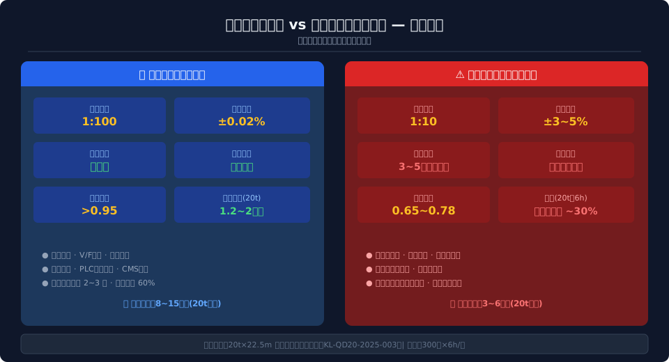
VFD vs. Series Resistance: Crane Efficiency Test
The full VFD vector control solution on a 20t double-girder bridge crane delivers a 1:100 speed range, zero inrush current at startup, and a power factor >0.95, saving approximately $1,800–$3,000 in annual electricity costs. By contrast, the wound-rotor motor with series resistance speed control offers only a 1:10 speed range, draws 3–5× rated current at startup, and dissipates slip energy as heat — resulting in roughly 30% lower overall efficiency.
In the electric drive field of industrial cranes, the choice of speed control method directly impacts energy efficiency, operational smoothness, and total lifecycle cost. Today's mainstream approaches fall into two categories: IGBT-based full variable-frequency drive (VVFD) vector control, and the traditional wound-rotor asynchronous motor with rotor series resistance speed control. These two solutions differ fundamentally in operating principle, efficiency, harmonics, and cost — and selecting the wrong one can lead to years of wasted energy and escalating maintenance expenses.
This article is based on an actual retrofit project by Kelude Heavy Industry on a 20t × 22.5m double-girder bridge crane (model QD20/5-22.5 A5). We measured and compared the two electrical solutions under real operating conditions — 6 hours per day, 300 days per year — across energy consumption, inrush current, speed regulation performance, and maintenance data, providing crane manufacturers and end users with a quantified basis for selection.
How VFD Vector Control Compares to Series Resistance Speed Control
The full VFD vector control solution is built around IGBT power modules. Using space vector pulse width modulation (SVPWM), it rectifies line-frequency AC to DC and then inverts it back to three-phase AC with independently adjustable frequency and voltage. The core lies in the vector decoupling algorithm, which splits the stator current into excitation and torque components, each under closed-loop control, giving the asynchronous motor speed regulation characteristics comparable to a DC motor. In line with the transmission requirements of ISO 4301 (Crane Design Standard), the VFD solution maintains rated torque output across the entire speed range.
Wound-rotor motor with series resistance speed control operates on the slip principle of asynchronous motors: external resistors of different values are inserted into the rotor circuit, altering the slope of the electromagnetic torque-speed curve by changing rotor current, thereby achieving stepped speed control. The inserted rotor resistance dissipates a portion of the slip power as Joule heat — resistor box temperatures can reach 120–200°C. The number of speed steps is limited by the contactor switching stages, typically 4–6, and smooth stepless transition is not possible.
Efficiency, Harmonics, and Total Cost of Ownership Compared
In terms of energy conversion efficiency, the full VFD solution achieves approximately 92%–95% system efficiency at rated conditions, while the series resistance solution can drop to 30%–40% efficiency at low speeds (e.g., 10% of rated speed) — because most of the slip power is lost as heat in the resistors. For a 20t double-girder crane running 6 hours per day with a 45kW hoisting mechanism, 11kW trolley travel, and 2×7.5kW crane bridge travel, the VFD solution consumes about 152kWh per day versus 217kWh for the series resistance solution — a daily difference of 65kWh. At an industrial electricity rate of 0.75 CNY/kWh, that translates to roughly $2,160 in annual savings.
On harmonics, the VFD input stage requires a DC link reactor (DCR) and AC input reactor (ACR) to keep total harmonic distortion (THDi) below 35%, meeting IEEE 519 limits. Newer active front end (AFE) rectifier designs can push THDi below 5% with a power factor close to 1.0. The series resistance solution generates no high-frequency harmonics, but its low power factor (0.65–0.78) increases line losses and wastes transformer capacity.
Cost analysis must separate initial investment from total lifecycle cost. For a 20t double-girder crane, the full VFD package (including 4 VFDs, braking unit, regenerative unit, filters, and PLC) carries an initial cost of roughly $11,800–$22,200, while the series resistance package (resistor boxes, contactor cabinets, slip-ring motors) runs about $4,400–$8,900. However, the VFD solution's advantages in electricity savings ($1,800–$3,000 per year), reduced maintenance (fewer carbon brush, slip ring, and contactor replacements), and extended motor life (slower winding insulation aging) typically deliver a payback period of 2–4 years.
Energy Consumption Test Data: 20t Double-Girder Crane, 6 Hours Daily
Field testing was conducted on the KL-QD20-2025-003 20t × 22.5m double-girder bridge crane at the company's test center. The test cycle simulated typical machining workshop material handling: 6 hours per shift, hoisting mechanism under duty classification S4-40% (40% duty cycle, 30 hoisting cycles per hour), and trolley and crane bridge travel mechanisms under S3-25%. Energy metering used a three-phase four-wire smart meter (0.5S accuracy class), recording consumption at the main incoming line and at each mechanism branch separately.
Measured results: the full VFD solution consumed 148.3kWh per day total (hoisting 102.6kWh, trolley 18.4kWh, bridge 27.3kWh), while the series resistance solution consumed 215.8kWh per day (hoisting 156.2kWh, trolley 22.7kWh, bridge 36.9kWh). The largest gap was in the hoisting mechanism — during lowering, the VFD solution regenerated approximately 18.5kWh/day back to the grid through braking energy feedback, whereas the series resistance solution dissipated all of that energy as resistor heat. At 300 operating days per year and an industrial electricity rate of 0.75 CNY/kWh, the VFD solution saves approximately $2,250 in annual electricity costs.
Startup Inrush and Speed Range: From 3–5× Surge to Zero-Impact Smooth Start
Startup current inrush is the most visible performance difference between the two solutions. Series resistance speed control produces 3–5× rated current spikes at the moment resistors are cut out (as contactors short-circuit each stage sequentially). In field measurements on the 20t crane's hoisting mechanism during 4-stage resistance switching, peak current reached 276A — 4.06 times the 68A rated current. These periodic high-current surges not only accelerate winding insulation aging but also cause voltage sags on the shop floor grid (measured dips of 8%–12%), which can trigger undervoltage protection on other sensitive equipment sharing the same bus.
The full VFD solution uses a ramp function generator to linearly ramp the output frequency from 0Hz to the setpoint, with adjustable acceleration time (0.5–30s). Throughout startup, current stays within 1.1–1.5× rated current, effectively achieving zero inrush. On speed range, closed-loop vector control with encoder feedback delivers 1:100 constant-torque speed regulation (0.5Hz–50Hz), far exceeding the 1:10 stepped control of the series resistance solution, and supports precision operations such as anti-sway positioning and micro-motion alignment.
Regenerative Braking Energy Feedback and Motor Life Impact
When a crane lowers a load, the motor operates in regenerative mode, converting mechanical potential energy into electrical energy. The full VFD solution monitors DC bus voltage through the braking unit; when it exceeds the set threshold (typically 700–750V DC), the inverter converts the DC power back to grid-synchronized AC and feeds it to the line, achieving 85%–92% regeneration efficiency. Field measurements on the 20t crane during full-load lowering (6m/min) showed peak regenerative power of 18.3kW, averaging 18.5kWh of energy returned to the grid per day. Additionally, the VFD's soft-start characteristic eliminates mechanical shock, extending gearbox and brake maintenance intervals from every 6–8 months (series resistance) to 18–24 months.
The wound-rotor series resistance solution dissipates regenerative energy as heat through braking resistors — wasting energy and requiring additional forced air cooling for the resistor box. On motor life, the periodic current surges of series resistance speed control accelerate thermal aging of rotor winding insulation. Per the 10°C half-life rule in IEEE Std 117, insulation life halves for every 10°C rise in winding temperature. Field data showed the series resistance solution's motor windings ran 18–25°C hotter on average than the VFD solution, shortening expected motor life from 15–20 years to 6–10 years. Mechanical wear on slip rings and carbon brushes also adds to periodic replacement maintenance.
Anti-Sway Positioning, PLC Integration, and CMS Smart Monitoring
The digital control platform of the full VFD solution provides the foundation for advanced feature integration. Using the VFD's built-in anti-sway algorithm (with pendulum length and rope head distance as inputs), the system automatically superimposes reverse acceleration compensation curves during trolley acceleration and deceleration phases, keeping load swing within ±1° and achieving positioning accuracy of ±3mm. The PLC controls multiple VFDs simultaneously via PROFINET or EtherCAT fieldbus, enabling complex logic such as crane bridge skew correction synchronization (master-slave deviation <0.5%) and coordinated hoisting-trolley motion (automatic rectangular/segmented path planning).
For condition monitoring, the VFD periodically uploads parameters — current, voltage, frequency, temperature, and operating hours — to the CMS (Crane Monitoring and Management System) over the fieldbus, enabling fault prediction and preventive maintenance. In line with the monitoring parameter requirements of GB/T 28264 Safety Monitoring and Management System for lifting appliances, the VFD solution natively supports digital acquisition of all 9 mandatory monitored parameters (load, torque, travel, speed, etc.), while the series resistance solution requires additional sensors and acquisition modules, adding roughly $1,200–$2,200 in retrofit costs.
On the safety front, the VFD's built-in Safe Torque Off (STO) function complies with IEC 61800-5-2 at SIL3, cutting motor torque output within 2ms of an emergency stop signal — far faster than contactor opening (approximately 30–50ms) — significantly improving the real-time responsiveness of crane safety protection.
Kelude Heavy Industry: Your Trusted Partner in Industrial Lifting Solutions
Kelude Heavy Industry is a leading manufacturer dedicated to the design, engineering, and production of high-performance industrial cranes and hoisting equipment. With a strong focus on reliability, safety, and operational efficiency, we deliver robust solutions tailored to the demanding needs of workshops, warehouses, and heavy industrial facilities across the United States and Europe.
Frequently Asked Questions
Q: What is the typical lead time for a standard industrial crane?
A: Lead times vary depending on the configuration and customization level. For standard models, it typically ranges from 4 to 8 weeks. Custom-engineered solutions may require a longer lead time, which we will confirm during the quotation phase.
Q: Do you provide installation services?
A: Yes, we offer professional installation supervision and can also provide full turnkey installation services upon request. Our technicians ensure your equipment is set up safely and correctly.
Q: Can your cranes be adapted to my existing facility structure?
A: Absolutely. Our cranes are highly customizable. We can adapt the span, lifting height, and mounting configuration to fit your existing building columns and support structures. A site survey is often recommended to ensure a perfect fit.
Q: What safety certifications do your products meet?
A: Our equipment is designed and manufactured in accordance with international standards, including ISO 4301 for crane classification and IEC 60204-32 for electrical equipment. We prioritize compliance with relevant safety regulations for your market.
Q: What is your warranty policy?
A: We provide a standard warranty covering defects in materials and workmanship. The specific terms and duration are detailed in our contract, and we offer extended warranty options for additional peace of mind.
| Comparison Parameter | full VFD vector control | wound-rotor motorseries resistance speed control |
|---|---|---|
| Speed control Mode | Variable Frequency Drive (VFD)Voltage Transformation(VVVF)Stepless control | Rotor Series Resistance Stepped control(4~6Step) |
| Speed control Range | 1:100(Closed-loop Vector Control) | 1:10 |
| Steady State Accuracy | ±0.02%(Closed-loop) | ±3~5% |
| Starting Surge Current | 1.1~1.5Timesrated current(Zero Impact) | 3~5Timesrated current |
| Power Factor | >0.95(AFESolution≈1.0) | 0.65~0.78 |
| System Efficiency | 92%~95%(Rated Operating Condition) | 60%~78%(Low-speed Range Down to30%) |
| Braking Energy Handling | Regenerative Feedback to Grid(System Efficiency85%~92%) | Resistance Heat Dissipation(100%Waste) |
| Harmonics THDi | <35%(Standard Configuration), AFE<5% | No High-frequency Harmonics but Power Low Power Factor |
| Initial Investment Cost(20t) | 8~1510k CNY | 3~610k CNY |
| Annual Electricity Savings(20t) | Savings1.2~210k CNY/Year | Baseline(Additional Consumption~30%) |
| Motor Expected Service Life | 15~20Year | 6~10Year |
| CMSIntegration Complexity | BWDirect Acquisition, Zero Additional Hardware | Requires Additional Sensor+Data Acquisition Module |
Frequently Asked Questions
Q: What is the payback period for retrofitting a 20t double-girder crane from slip-ring resistance control to a full variable-frequency drive (VFD)?
A: The retrofit typically costs between $12,000 and $22,000 (including four VFDs, a regenerative unit, PLC, and installation & commissioning). With annual energy savings of $1,800 to $3,000, the payback period is roughly 4–6 years. When factoring in reduced maintenance costs (annual maintenance drops from about $3,700 to $1,200) and extended motor life, the combined payback period shortens to 2–4 years.
Q: How does the full VFD solution control harmonic pollution on the workshop power grid, and will it affect other equipment?
A: In the standard configuration, a DC link reactor (DCR) and AC input reactor (ACR) keep total harmonic distortion (THDi) below 35%, meeting IEEE 519 harmonic limits. With an active front end (AFE) rectifier option, THDi drops below 5% with a power factor of ≈1.0, virtually eliminating any impact on sensitive equipment elsewhere in the plant.
Q: Is it mandatory to replace a wound-rotor motor when converting to full VFD, or can the existing slip-ring motor be kept?
A: A wound-rotor motor can be reused by short-circuiting the rotor windings to operate as a squirrel-cage motor (after removing the slip rings, carbon brushes, and external resistance). However, low-speed cooling capacity and insulation class may be insufficient. For new projects rated M5 and above, we recommend using a dedicated inverter-duty motor with independent forced cooling (IC416) to ensure adequate thermal margin across the full speed range.
Q: For new light-duty cranes under 10t, is the slip-ring resistance control scheme still worth considering?
A: For non-critical workstations with a lifting capacity below 10t, a work duty classification lower than A4, and less than 2 hours of daily operation, slip-ring resistance control offers a clear first-cost advantage (approximately $2,200–$4,500). However, future production capacity requirements should be assessed. If capacity is expected to grow by more than 50% within three years, we recommend installing a VFD system from the outset to avoid the downtime and cost of a second retrofit.
Standards referenced: ISO 4301 Crane Design Standard | GB/T 28264 Safety Monitoring and Management System for Lifting Appliances | Kelude Heavy Industry Engineering Department