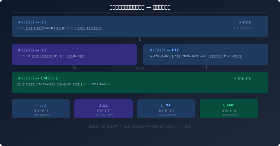
Crane Electrical Control System 4-in-1: VFD, Anti-Sway, PLC
The crane's Electrical Control System is the machine's central nervous system—from inverter drive and anti-sway positioning to PLC logic control and CMS remote operation & maintenance, four subsystems work in concert to form a complete Smart Crane electrical architecture. This four-part series draws on real-world Kelude Heavy Industry engineering projects, covering VFD selection and sizing, anti-sway control algorithms, PLC system design, and CMS condition monitoring. With 12 comparison tables and 16 FAQ pairs across the series, it delivers a reusable methodology for crane electrical design.
Smart Crane Electrical System: The Four Core Subsystems
| # | Subsystem | Core Content | Article |
|---|---|---|---|
| | Frequency Inverter / VFDSelection Guide | Vector Control·Braking Resistor·Harmonic Mitigation Full-Process Calculation | Read |
| ① | Anti-Sway Control | Electronics Anti-swayand Machinery Anti-sway Technical Comparison | Read |
| ② | PLC Control System | I/OLoad Distribution in Multi-Crane Coordinated Design Example | Read |
| ③ | CMSCondition Monitoring | Remote Operation & Maintenance Implementation Guide | Read |
How the Four Systems Work Together: A Layered Architecture
The four subsystems are not isolated from one another—they form a progressive architecture that spans from the underlying drive layer to top-level operational management:
① VFD (Bottom Drive Layer) — Supplies variable-speed power to the motor and serves as the foundation of the electrical system. The VFD selection (power/voltage/control method) directly defines the design boundaries for the other three systems: the braking resistor capacity determines the energy feedback capability during anti-sway operation; the PLC reads VFD status via communication protocols (Profinet/Modbus); and the CMS collects current/frequency/temperature data from the VFD.
② Anti-Sway Control (Motion Control Layer) — Builds on the speed-controlled foundation provided by the VFD by adding swing-angle suppression algorithms. Open-loop input shaping is implemented within the PLC (with no additional hardware cost), while closed-loop swing-angle feedback requires extra sensors (cameras/laser) that send the swing-angle signal back to the PLC for closed-loop control. Anti-sway is tightly coupled with the VFD's acceleration/deceleration ramp parameters—an overly steep S-curve amplifies oscillation, while an overly gentle curve sacrifices efficiency.
③ PLC (Logic Control Layer) — Acts as the machine's brain, communicating bidirectionally with both the VFD (control commands) and the anti-sway sensors (feedback signals), while executing safety circuit checks, operating mode switching, and multi-crane coordinated operation. The PLC's I/O configuration and communication architecture directly determine how fully the VFD and anti-sway functions can be realized.
④ CMS (Intelligent Operations Layer) — Aggregates data from three sources: the VFD (current/temperature), the PLC (runtime hours/fault codes), and additional sensors (vibration/oil temperature), then uploads it to the cloud platform via 4G/5G for remote monitoring and fault prediction. The CMS serves as the data convergence point and value amplifier for the three layers below it.
System Coupling Matrix: Key Interdependencies
| Subsystem A Subsystem B | Coupling Relationship | Key Parameter |
|---|---|---|
| Frequency Inverter / VFD anti-sway control | Acceleration/Deceleration Limitation Sway Angle Suppression | SCurve Slope, Braking Resistor Power |
| Frequency Inverter / VFD PLC | Speed Command/State Feedback/Fault Code | Profinet/CANopen PDOMapping |
| Frequency Inverter / VFD CMS | Three-Phase Current/Frequency/Temperature/Operating Time | Modbus RTUregister Address |
| anti-sway control PLC | Sway Angle Feedback PLC Corrects Speed Setpoint | AISampling Period, PIDParameter |
| PLC CMS | Fault code/Event Log/I/OStatus | MQTTTopic/JSONFormat |
| CMS Cloud Platform | Historical Data/Trend Analysis/Alarm Notification | 4G/5G MQTT Qo S=1 |
Why One Consistent Case Study Across All Four Articles?
This four-part series uses a single 20t A5 double-girder bridge crane as the design case throughout (lifting speed 5/0.8 m/min, crane bridge travel speed 3–30 m/min, trolley speed 2–20 m/min, 380V/50Hz power supply). Parameters are cross-referenced across subsystems: the braking resistor power (12kW/6Ω) calculated in the VFD article feeds into the energy feedback analysis in the anti-sway article; the I/O allocation table in the PLC article is based on the VFD count and control scheme established in the VFD article; and the sensor mounting positions in the CMS article follow the hardware layout defined in the VFD and PLC articles. This interconnected case-study approach means the four articles can be read independently or as a complete design handbook when read in sequence.
Frequently Asked Questions
Q: Is there a required reading order for the four articles?
A: We recommend reading in the order ① VFD → ② Anti-sway → ③ PLC → ④ CMS, since the hardware selections in each article serve as the calculation inputs for the next. If you're only interested in a specific subsystem, each article stands alone—all required design parameters for that subsystem are included at the end of the article, with no dependency on earlier content. If you already have a crane and want to retrofit a CMS, you can skip straight to Article ④.
Q: How does this electrical four-part series relate to the earlier "Hoisting Mechanism Selection" series?
A: The two series are complementary—the hoisting mechanism series (motor, gearbox, drum, brake) covers the crane's mechanical power train, while the electrical four-part series (VFD, anti-sway, PLC, CMS) covers the crane's electrical control chain. Mechanical and electrical systems are two dimensions of the same crane: the YZR180L-6 motor selected in the hoisting series requires the VFD article here for drive matching, and the brake selection results from that series determine the safety-circuit I/O design in the PLC article. Together, the two series form a complete crane engineering knowledge base spanning from mechanical design to electrical control.
Q: Can this electrical solution be directly applied to cranes of other capacities?
A: For cranes under 20t (5–16t), the solution can be reused directly—only the VFD power rating and braking resistor values need adjustment. For 32t–50t cranes, upgrade to heavy-duty VFDs (G-type/P-type) and increase the number of parallel braking units (doubling resistor power). Above 50t, we recommend upgrading the PLC to the S7-1500 series (larger program memory + more Profinet ports) and upgrading CMS sensors from single-axis to tri-axis vibration monitoring (MEMS accelerometers). Refer to the "Parameter Quick Reference Tables" in each article for the full capacity-to-configuration mapping.
Q: Will there be additional articles on electrical topics in the future?
A: The four-part series covers the four core electrical subsystems of a crane. Potential future topics include: ① Safety PLC and functional safety (IEC 61508 SIL2/SIL3 certification design); ② In-depth industrial Ethernet comparison (measured performance data for Profinet/EtherCAT/EtherNet/IP on cranes); ③ Digital Twin and virtual commissioning (using Siemens MCD or Unity for virtual simulation of PLC programs); ④ AI-based fault prediction (LSTM/Transformer applied to CMS time-series data). Let us know if you'd like us to dive deeper into any of these areas.
Standards referenced: ISO 4301 Crane Design Standard · IEC 61508 Functional Safety · IEC 60204-32 Safety Requirements for Electrical Equipment of Cranes · ISO 12480 Condition Monitoring General Principles | Technical Department