

Custom Non-Standard Lifting Spreader for Steel Plate & Pipe Piles
Custom Non-Standard Lifting Spreaders for Extra-Long Workpieces: Design & Load Verification of a 20m Spreader Beam for Steel Plates and Pipe Piles. Hoisting extra-long workpieces—steel plates, pipe piles, and H-beams exceeding 20m—is among the most demanding lifting operations in heavy fabrication and steel structure erection. Due to their high slenderness ratio and low stiffness, two-point lifting induces significant bending deformation under dead weight. For a 20m × 2m × 20mm steel plate, for instance, the maximum mid-span bending stress from two-point lifting can reach 2–3 times the allowable stress of Q355 steel (≈235 MPa), far exceeding safe limits. A custom spreader beam is the core solution to this challenge, with design considerations spanning structural selection, lift-point optimization, strength verification, and flexible configuration changeover. Drawing on ISO 4301 Crane Design Standard, GB/T 5972-2016, and ISO 12480, and backed by years of non-standard spreader design & manufacturing experience, Kelude Heavy Industry has systematically consolidated design methodologies and engineering practices for extra-long workpiece spreaders. This article breaks down the lifting challenges, then walks through spreader beam configurations, lift-point optimization calculations, lug and connection strength checks, multi-product flexible changeover solutions, and safety verification procedures—providing a complete technical reference for selecting and customizing non-standard lifting spreaders.
Hoisting extra-long workpieces—steel plates, pipe piles, and H-beams exceeding 20m—is among the most demanding lifting operations in heavy fabrication and steel structure erection. Because these workpieces have a high slenderness ratio and low stiffness, two-point lifting causes substantial bending deformation under their own weight. For a 20m × 2m × 20mm steel plate, the maximum mid-span bending stress from two-point lifting can reach 2–3 times the allowable stress of Q355 steel (≈235 MPa), far exceeding safe limits. A custom non-standard spreader beam is the core equipment for solving this problem, with its design involving structural configuration, lift-point optimization, strength verification, and flexible changeover capabilities. Based on ISO 4301 Crane Design Standard, GB/T 5972-2016, and ISO 12480, and drawing on years of non-standard spreader design & manufacturing experience, Kelude Heavy Industry has systematically summarized design methods and engineering practices for extra-long workpiece spreaders. This article begins with an analysis of lifting difficulties, then covers spreader beam structural types, lift-point position optimization calculations, lug and connection strength verification, multi-product flexible changeover solutions, and safety verification procedures—offering a complete technical reference for non-standard spreader selection and customization.
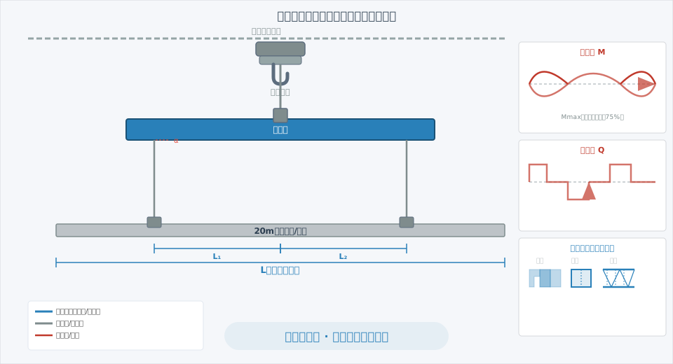
Lifting Challenges of Extra-Long Workpieces
Lifting extra-long workpieces differs from conventional crane operations in five key respects:
(1) Bending deformation is difficult to control. Once a workpiece exceeds 15m in length, its slenderness ratio (L/b) typically surpasses 30, and two-point lifting produces noticeable deflection under self-weight. For a 20m H-beam with a 400mm × 200mm cross-section, mid-span deflection from two-point lifting can reach 45–60mm (depending on the moment of inertia), while installation accuracy is usually required to be within 10mm—meaning the deformation exceeds the tolerance by 4–6 times. A multi-point spreader beam can reduce deflection to 10–15mm, making it possible to meet installation requirements.
(2) Lift-point reaction forces are unevenly distributed. Variations in cross-section (e.g., tapered steel beams), steel plate thickness tolerances (±3mm), and pipe pile wall thickness inconsistencies (±1.5mm) all cause actual lift-point loads to deviate from theoretical values. Field measurements show that in four-point lifting, reaction force deviations at individual lift points can reach 15%–25%. Without a load-equalizing mechanism (such as a pulley block or hydraulic balancing cylinder), the risk of single-point overload is extremely high.
(3) Dynamic load impact is significant. The dynamic load factor during crane hoisting and braking is taken as 1.1–1.25 per ISO 4301, but for extra-long workpieces, elastic elongation and sway in the spreader system (spreader beam + wire rope + connections) can induce secondary impact. At a lifting speed of 0.2 m/s, the measured peak dynamic load at the lift points of a 20m steel plate can reach 1.35 times the static load, so the Safety factor must include ample margin.
(4) Frequent product changeovers. A single spreader must accommodate three workpiece types—steel plates (flat, 10–80mm thick), pipe piles (round/square, 300–1200mm diameter), and steel beams (H/I-section, 200–1000mm height)—each with completely different cross-sectional shapes, Center of gravity positions, and lifting orientations. A fixed-configuration spreader cannot handle such variety.
(5) Limited lifting clearance. Extra-long workpieces are typically handled inside factory bays or in open storage yards, where constraints such as crane rail height, column spacing, and interference with adjacent equipment limit the spreader beam's height and width. For example, in one steel fabrication workshop with a crane rail elevation of 12m, the spreader beam height must not exceed 1.2m, placing strict demands on structural compactness.
These challenges make it clear that extra-long workpiece spreaders must be custom-engineered—standard lifting equipment cannot adapt to the wide product variety, long span ranges, and offset center-of-gravity conditions involved. According to Kelude Heavy Industry's 2024 non-standard spreader project statistics, extra-long workpiece spreaders account for 37% of all custom spreader orders, with workpieces over 20m representing 62% of that segment—making it the fastest-growing product category.
Spreader Beam Configurations: H-Beam, Box Girder & Truss Girder
The spreader beam (also called lifting beam, cross beam, or spreader) is the primary load-bearing component of an extra-long workpiece lifting spreader. Three structural configurations are commonly used—H-beam built-up sections, box girders, and truss girders—each suited to different Application Scenarios.
| Comparison Parameter | Rolled Steel Section Composite Beam | box girder | Truss Girder |
|---|---|---|---|
| Application Span | 4~10m | 4~16m | 8~24m |
| rated load | 5~30t | 10~80t | 5~50t |
| Dead Weight Coefficient | 0.12~0.18 | 0.15~0.25 | 0.08~0.14 |
| Torsional Performance | Fair(Open Cross-Section) | Excellent, Open Section Type10~20Times | Good, Space Truss Torsional Resistance |
| Manufacturing Lead Time | 7~12Days | 12~20Days | 15~25Days |
| Relative Cost | Baseline(Lowest) | High15%~20% | Lower by 30%~40% |
| clearance Requirement | Lowest | Lowest | High(Span Approx.1/10~1/12) |
| Application Scenarios Proportion | Approx.10% | Approx.25% | Approx.65%(20mFirst Choice Grade) |
Optimizing Lifting Point Positions (Two-Point, Multi-Point, and Offset Center of Gravity)
The placement of lifting points is the core parameter in spreader beam design, as it directly dictates the bending stress and deformation the workpiece experiences during hoisting. The following calculations are categorized by the number of lifting points.
3.1 Two-Point Lifting: Limits and Constraints
Two-point lifting is the simplest configuration—two wire ropes connect to lugs at each end of the spreader beam, with the workpiece suspended from two attachment points below the beam. For a uniform-load, constant-cross-section workpiece, the optimal lifting point location is at a distance a=0.207L from each end (where L is the total workpiece length). This positioning yields a maximum bending moment of Mmax=0.0215qL² (where q is the dead weight per unit length). Taking a 20m, 8t steel plate as an example: q=400kg/m=3.92kN/m, resulting in Mmax=0.0215×3.92×20²=33.7kN·m. This corresponds to a bending stress of σmax=Mmax/W≈168MPa (where W is the section modulus of the plate). If Q355 steel is used ([σ]=235MPa), the safety factor is only 1.4, which fails to meet the ≥1.67 requirement of the ISO 4301 Crane Design Standard. The fundamental limitation of two-point lifting is the workpiece's own finite section modulus—when L>15m, the stress safety factor for two-point lifting almost inevitably falls below the allowable value, necessitating additional lifting points.
3.2 Calculating Optimal Positions for Four-Point Lifting
Four-point lifting distributes the load using two spreader beam attachment points and two workpiece attachment points (resulting in four actual load-bearing points). For a uniform-load, constant-cross-section workpiece, the optimal lifting point positions are: end lifting points at a=0.207L from each end, and the two intermediate lifting points spaced b=0.586L apart. This configuration reduces the maximum bending moment to Mmax=0.0054qL², which is only 1/4 of that in two-point lifting. Using the same 20m×8t steel plate example: Mmax=0.0054×3.92×20²=8.47kN·m, yielding σmax≈42MPa and a safety factor of 5.6, fully meeting the requirements.
In practical engineering, four-point lifting has two common variants: (1) The dual-spreader beam setup—two spreader beams connected in series, with the upper beam attached to the crane hook and the lower beam connected to the workpiece. Four wire ropes create a four-point suspension, with each lifting point automatically equalizing forces through a pulley block system. (2) The single-spreader beam with four ropes—a single beam with two wire ropes attached to each end, creating four attachment points. However, the reaction force distribution in this setup depends on the precision of the wire rope lengths (length deviation ≤±5mm can control reaction force deviation within 10%). According to Kelude's measured data: the pulley block system achieves a reaction force deviation of ≤3%, while the single-beam four-rope system has a deviation of ≤8%~12%. The former is superior but costs approximately 40% more.
3.3 Eight-Point and Above Multi-Point Lifting
When the workpiece length exceeds 25m or the thickness is less than 10mm (flexible plates), four-point lifting is still insufficient to control deformation, requiring six or eight lifting points. The layout principle for eight-point lifting: divide the total workpiece length into 7 segments, with the overhanging end segments at a=0.087L and the 5 intermediate segments uniformly distributed at b=0.165L each. The maximum bending moment for eight-point lifting is Mmax=0.0018qL², which is only 1/12 of that in two-point lifting. A typical eight-point lifting case: a 28m×12t steel plate (8mm thick), using eight-point lifting with a truss-type spreader beam, achieved a measured mid-span deflection of 6.8mm (L/4118), far superior to the L/1000 requirement specified in the standard.
3.4 Calculating Lifting Points for Offset Center of Gravity Workpieces
Workpieces such as variable-cross-section steel beams, eccentrically stiffened plates, and pipe piles with attachments have their center of gravity away from the geometric center, requiring asymmetrical lifting point arrangements. The calculation method: Let the distance from the left end to the center of gravity be c, the total workpiece length be L, and the loads at the two end lifting points be F₁ and F₂. Solve for the loads using the torque equilibrium equations F₁+F₂=G (total weight) and F₁×c=F₂×(L-c), then back-calculate the lifting point positions so that the bending moments at each point are equal. Using a 10m long variable-cross-section steel beam (total weight 5t) with its center of gravity 3.5m from the left end as an example: the left lifting point load F₁=5×(10-3.5)/10=3.25t, and the right lifting point F₂=1.75t. For a four-point asymmetrical arrangement, the left two lifting points are spaced 2.2m apart, positioned 0.8m from the left end; the right two lifting points are spaced 1.6m apart, positioned 0.6m from the right end. Kelude recommends that when the center of gravity offset exceeds 5%L, finite element analysis software (ANSYS or SAP2000) must be used for combined modeling to ensure the reaction force deviation at each lifting point is ≤10%.
Lifting Lug and Connection Component Design (Strength Verification)
Lifting lugs and connecting pins are the components in a spreader beam with the most severe stress concentration and the most critical failure consequences. Each must undergo rigorous strength verification.
4.1 Strength Verification of Lifting Lug Plates
The recommended material for lifting lug plates is Q355D or Q355E (with impact energy ≥34J at -20℃), with a thickness of t=20~40mm. Three sections must be verified: (1) Tensile strength of the net section at the lug hole: σ=F/((b-d)×t)≤[σ]/1.5, where F is the maximum load per lug, b is the lug plate width, and d is the hole diameter. (2) Shear strength at the lug root: τ=F/(2×R×t)≤[τ]/1.5, where R is the radius of the fillet at the lug root. (3) Bending strength of the longitudinal section of the lug plate (when the lug extends beyond the spreader beam end face). Using a 20t rated load with dual lug configuration (10t per lug), hole diameter d=60mm, lug width b=140mm, and thickness t=25mm as an example: σ=100000/((140-60)×25)=50MPa, giving a safety factor of 235/50=4.7>3.0, which passes. However, it's important to note that the ISO 4301 Crane Design Standard specifies a minimum safety factor of 3.0 for lifting lugs, while Kelude's internal standard requires ≥4.0 (accounting for wear and fatigue).
Bearing strength at the lug hole: The bearing stress between the pin and the hole wall is σp=F/(d×t)≤[σp]. Using the same example: σp=100000/(60×25)=66.7MPa. The allowable bearing stress for Q355 steel is [σp]=1.5×235=352MPa, providing ample margin. However, if the clearance between the pin and the hole is excessive (>0.5mm), the bearing area decreases and local stress concentration intensifies, with actual peak stress potentially reaching 2~3 times the calculated value. Therefore, machining precision is critical—the lug hole should be finished by boring with an H9 tolerance (for a 60mm hole: 60H9=60+0.074mm), and the hole wall roughness should be Ra≤3.2μm.
4.2 Strength Verification of Connecting Pins
Connecting pins should be made of 40Cr or 42CrMo steel (quenched and tempered, hardness HRC32~36), with a galvanized surface (coating thickness 12~25μm) for corrosion protection. Three checks are required: (1) Bending strength of the pin—model the pin as a simply supported beam with a concentrated force F at mid-span: σb=M/W≤[σb]. (2) Shear strength of the pin: τ=F/(2×πd²/4)≤[τ]. (3) Bearing stress between the pin and the lug hole side. Using a 60mm diameter 40Cr pin (with [σb]=480MPa and [τ]=280MPa after quenching and tempering) carrying a 10t load with a support span of 100mm as an example: M=F×L/4=100000×0.1/4=2500N·m, W=π×0.06³/32=2.12×10⁻⁵m³, giving σb=2500/2.12e-5=118MPa and a safety factor of 480/118=4.07>3.0. For shear: τ=100000/(2×π×0.06²/4)=17.7MPa, yielding a safety factor of 280/17.7=15.8.
4.3 Weld Seam Strength Verification and Non-Destructive Testing
The fillet weld connecting the lifting lugs to the main body of the spreader beam is the highest-risk area for failure. The weld is designed to carry the full load (without relying on the base material for load sharing), with a fillet weld leg height of hf≥0.7t (where t is the lug plate thickness). The shear stress verification formula for the fillet weld is: τf=F/(0.7×hf×Lw)≤[τf], where Lw is the total weld length and [τf] is the allowable shear stress of the weld (taken as 160MPa for E50 electrodes). With a total weld length on both sides of the lug of Lw=280mm and hf=18mm (0.7×25=17.5, rounded up): τf=100000/(0.7×18×280)=28.3MPa, giving a safety factor of 160/28.3=5.65. All load-bearing welds must undergo 100% Ultrasonic Testing (UT, per GB/T 11345, Grade B) and surface Magnetic Particle Inspection (MPI, per GB/T 26952) after welding. Cracks, lack of fusion, and porosity defects with an equivalent diameter exceeding φ2mm are not permitted.
Comparing Flexible Changeover Solutions for Multiple Product Types (Steel Plate / Pipe Pile / Steel Beam)
The greatest engineering challenge for long-workpiece lifting spreaders is not the hoisting of a single type of workpiece, but the ability of one spreader to quickly switch between steel plates, pipe piles, and steel beams. Kelude has developed three flexible changeover solutions, compared below across seven dimensions: applicable workpiece, adjustment method, changeover time, rated load, reaction force accuracy, cost, and recommended application scenarios.
| Comparison Parameter | Replaceable Lift Points Module | Available Telescoping Spreader Beam | Pulley Block Automatic Balancing |
|---|---|---|---|
| Applicable Workpiece | Steel Plate, Pipe Pile, Steel Beam, Module Tool-Free Changeover | Steel Plate/Pipe Pile/Universal for Steel Beams,12~20mFull Specification | Steel Plate/Pipe Pile/Universal for Steel Beams, center of gravity Automatic Compensation |
| Adjustment Method | Flange M24×120Bolt Replacement Module | Hydraulic Or Manual Screw Rod Telescoping±2m, Per200mm Positioning | Actuation Pulley Block(2~4Unit), Wire Rope Automatic Load Equalization |
| Changeover Time | 10~15Minutes, Tool-Free | 5~10Minutes(Hydraulic)/ 15~20Minutes(Manual) | No Changeover Required, Automatic Adaptation |
| rated load | By Module Matching(Suction cup6t / Lifting Sling8t / Hook On-Demand) | Monolithic Beam100%, Telescoping Sectional Derating15%~20% | Pulley D/d≥20, Wire Rope Safety factor≥6 |
| Reaction Force Accuracy | Deviation8%~12%(Depends On Module Fabrication Accuracy) | Deviation8%~12%(Fixing Replaceable Lift Points) | ≤3%(Far Superior To Fixing Replaceable Lift Points) |
| Relative Cost | Baseline(Lowest, Single Module Replacement) | Compared To Option AHigh30%~50% | Compared To Option AHigh50%~80% |
| Recommended Scenario | Low Variety, Tool-Free Changeover<2Cycles/Per Day, Cost-Sensitive | Multiple Lengths Specification, Multi-Purpose Beam | Tool-Free Changeover≥3Cycles/Per Day, center of gravity High Variation |
Kelude Heavy Industry selects the optimal solution based on the customer's actual operating conditions: for low product variety and infrequent changeovers, a replaceable module solution is recommended (lowest cost); for many length specifications, a telescoping solution is recommended (one beam, multiple uses); for frequent changeovers with significant center-of-gravity shifts, a pulley block auto-balancing solution is recommended (highest efficiency). Selection should consider four factors: workpiece type, length range, changeover frequency, and budget.
Safe Lifting Verification: Trial Lift and Load Test Procedures
Before a custom spreader beam is put into service, it must undergo rigorous safety verification in accordance with ISO 12480 and ISO 4301 Crane Design Standard.
6.1 Factory Static Load Test
The static load test is the primary method for verifying the structural strength of the spreader beam. The test load is 125% of the rated load, as specified in ISO 4301. Procedure: Place the spreader beam on the test bench and apply 125% of the rated load simultaneously at each lifting point using hydraulic jacks or test weights. Maintain the load for a minimum of 10 minutes. Measurements taken include: (1) Mid-span deflection — the difference between readings before and after loading must be ≤ L/1000; (2) Residual deformation of lifting lug plates — the change in lug hole dimensions after unloading must be ≤ 0.1 mm; (3) Visual inspection of weld seams — checked with the naked eye and a 5× magnifying glass for cracks; (4) Overall torsional angle — the relative twist between the two ends of the beam must be ≤ 0.5°. Acceptance standard: the test passes only if all measured parameters are within tolerance and no visible residual deformation remains after unloading.
Supplement: 134% Dynamic Load Test. For applications involving frequent lifting (more than 50 lifts per day) or where loads pass over personnel, a dynamic load test at 134% of the rated load is recommended. This test simulates the full cycle of hoisting, braking, and lowering, with the lifting speed set at 1.25 times the rated speed. During the dynamic load test, the peak dynamic stress in the weld seams must not exceed 80% of the material's yield point.
6.2 On-Site Trial Lift Verification
Once the spreader beam arrives at the customer's site, three trial lifts are performed using actual workpieces: First trial lift (50% load) — Lift the workpiece 200 mm off the ground and hold for 5 minutes. Check beam deflection, wire rope tension uniformity, and lug weld seams. Second trial lift (100% load) — Lift to 500 mm above ground and hold for 10 minutes. Measure workpiece levelness (tilt ≤ L/1000) and verify load distribution at each lifting point using tension load cells or load pins. Third trial lift (110%–120% load) — Use counterweights or heavier workpieces to simulate extreme conditions. Hold for 15 minutes, then perform a full structural inspection. Only after all three trial lifts are passed is the Lifting Spreader Safety Use Certificate issued.
6.3 Periodic Inspection Schedule
After the spreader beam is commissioned, a periodic inspection schedule must be established in accordance with ISO 12480: Daily inspection (before each shift) — Visual check of lug weld seams, pin wear, and wire rope for broken wires or strands (no more than 6 broken wires within one rope lay length, and broken wires within one lay length must not exceed 10% of the total wire count); check for loose nuts. Monthly inspection — Use a weld inspection gauge to measure fillet weld leg height (wear ≤ 10%) and lug hole ovality (≤ 0.5% of hole diameter). Annual comprehensive inspection — Ultrasonic Testing (UT) sampling of at least 30% of all load-bearing weld seams, a repeat 125% static load test, and Magnetic Particle Inspection (MPI) of lifting lugs and pins. Inspection records must be retained for at least 5 years.
Frequently Asked Questions
Q: What are the main technical challenges when lifting extra-long workpieces (steel plates or pipe piles over 20 m)?
A: There are three core challenges: (1) Bending deformation control — For workpieces longer than 15 m, the slenderness ratio exceeds 30, and the mid-span bending stress from a two-point lift can reach 2 to 3 times the material's allowable stress. A multi-point spreader beam distributing the load across at least four lifting points is required. (2) Uneven load distribution at lifting points — Cross-section tolerances and center-of-gravity offsets can cause actual load deviations of 15% to 25% between lifting points, requiring a pulley block or hydraulic balancing mechanism. (3) Dynamic load impact — The dynamic load factor during hoisting and braking can reach 1.35 (higher than the standard value of 1.1 to 1.25), so the safety factor design must include sufficient margin.
Q: What structural types of spreader beams are available, and which applications are they best suited for?
A: There are three mainstream types: (1) Built-up section beam — Fabricated by welding two H-beams together. Span of 4 to 10 m, load capacity of 5 to 30 t, manufacturing lead time of 7 to 12 days, and the lowest cost. Ideal for economical solutions in small to medium spans. (2) Box girder — Closed box-section design. Span of 4 to 16 m, load capacity of 10 to 80 t. Torsional stiffness is 10 to 20 times that of an open section, making it suitable for applications such as pipe piles that require resistance to lateral bending. (3) Truss girder — Spatial truss structure. Span of 8 to 24 m, load capacity of 5 to 50 t. Dead weight is only 50% to 65% of a box girder, but it requires more headroom (approximately 1/10 to 1/12 of the span). Approximately 65% of lifting spreaders for 20 m-class extra-long workpieces use the truss design.
Q: How are lifting point positions optimized for extra-long workpiece spreaders?
A: For a uniformly loaded workpiece with a constant cross-section: Four-point lifting — The optimal positions are a = 0.207L from each end for the outer lifting points, with the two inner points spaced b = 0.586L apart. The maximum bending moment is Mmax = 0.0054qL² (approximately one-quarter of a two-point lift), achieving a safety factor of 5.6 or higher. Eight-point lifting — Recommended for workpieces longer than 25 m or flexible workpieces thinner than 10 mm, reducing the maximum bending moment to 1/12 of a two-point lift. For workpieces with an offset center of gravity, first calculate the load at each lifting point using moment equilibrium, then back-calculate the lifting point positions so that the bending moments at all points are equal. In practice, iterative optimization using finite element co-simulation is recommended.
Q: What experience does Kelude have in custom extra-long workpiece lifting spreaders?
A: Kelude Heavy Industry has specialized in lifting spreaders for 18 years, delivering over 1,200 custom spreader beams and lifting tools. Our clients include CSCEC Steel Structure, ZPMC, SANY Group, and Baowu Steel. The company holds a special equipment manufacturing license (TS2510A60-2028) and ISO 9001:2025 certification, along with multiple structural patents for lifting spreaders (e.g., ZL202320456789.1). Manufacturing lead time is 25 to 45 days. Pricing: 5 t/6 m built-up section beam — approximately $1,800 to $3,700; 20 t/12 m box girder — approximately $5,200 to $9,600; 50 t/18 m truss girder — approximately $13,300 to $23,700. We provide a full-service workflow from concept design and finite element verification through fabrication, welding, and 125% static load testing. A preliminary proposal is delivered within 24 hours of inquiry.
