

Harbor Crane VFD Retrofit with Synchronized Hoist, Luffing & Slewing
Custom Variable-Frequency Drive (VFD) Retrofit for Harbor Portal Cranes: Synchronized Commissioning of Hoisting, Luffing, and Slewing Mechanisms. Harbor portal cranes—also referred to as portal cranes or gantry cranes—are critical equipment for block lifting, berth assembly, and equipment installation in port and shipbuilding operations. They operate under high work duty classifications, frequent usage cycles, and widely varying load conditions. The traditional wound-rotor asynchronous motor with rotor series resistance speed control has long been the dominant solution. However, as shipyard production capacity expands and green shipbuilding practices gain traction, the inherent drawbacks of resistance-based speed control—energy losses of approximately 25%–35% due to resistor heat dissipation, a narrow speed ratio of only 1:3, severe mechanical shock, and frequent contactor and resistor burnouts—have become increasingly problematic. This custom full variable-frequency drive (VFD) retrofit replaces the original resistance-based speed control system with high-performance vector VFDs, integrated with PLC centralized control and industrial Ethernet Communication, enabling high-precision speed coordination and synchronized control across the hoisting, luffing, and slewing mechanisms. Drawing on Kelude Heavy Industry's recent experience in retrofitting multiple large harbor portal cranes, this article systematically outlines the complete technical workflow—from system design and VFD selection to synchronized commissioning and network integration—and references ISO 4301—2008 Crane Design Standard and GB/T 14406—2011 General Purpose Portal Cranes, providing actionable technical guidance for equipment management departments and retrofit engineering teams.
Harbor portal cranes—also referred to as portal cranes or gantry cranes—are critical equipment for block lifting, berth assembly, and equipment installation in port and shipbuilding operations. They operate under high work duty classifications, frequent usage cycles, and widely varying load conditions. The traditional wound-rotor asynchronous motor with rotor series resistance speed control has long been the dominant solution. However, as shipyard production capacity expands and green shipbuilding practices gain traction, the inherent drawbacks of resistance-based speed control—energy losses of approximately 25%–35% due to resistor heat dissipation, a narrow speed ratio of only 1:3, severe mechanical shock, and frequent contactor and resistor burnouts—have become increasingly problematic. This custom full variable-frequency drive (VFD) retrofit replaces the original resistance-based speed control system with high-performance vector VFDs, integrated with PLC centralized control and industrial Ethernet Communication, enabling high-precision speed coordination and synchronized control across the hoisting, luffing, and slewing mechanisms. Drawing on Kelude Heavy Industry's recent experience in retrofitting multiple large harbor portal cranes, this article systematically outlines the complete technical workflow—from system design and VFD selection to synchronized commissioning and network integration—and references ISO 4301—2008 Crane Design Standard and GB/T 14406—2011 General Purpose Portal Cranes, providing actionable technical guidance for equipment management departments and retrofit engineering teams.
Current-State Analysis of Harbor Portal Crane Performance
The primary technical parameters of harbor portal cranes include a hoisting capacity of 50t to 200t (with large shipbuilding portal cranes reaching 300t and above), a working radius of 25m to 45m, and a lifting height of 30m to 50m above the rail. A typical configuration employs three wound-rotor asynchronous motors driving the hoisting, luffing, and slewing mechanisms respectively, with multi-stage resistors connected in the rotor circuit and progressively shorted out by contactors to achieve stepped speed control. This conventional approach suffers from the following critical issues:
| Comparison Parameter | Conventional Resistance Speed control | Variable Frequency Drive (VFD)Retrofit Solution |
|---|---|---|
| Speed control Method | Wound-rotorasynchronous motor+Multi-stage rotor resistanceresistor, Contactor Progressive short-circuiting Stepped control | High-performance Vector VFDClosed-loop/Open-Loop Control, Stepless Speed control, Hoisting / Lifting With Encoder Achieve full torque at zero speed |
| Energy consumption and efficiency | Resistance Heat loss as percentage of input Power25%~35%,132kWMotor Annual wasted electricity cost approx.50,000 CNY | Overall energy saving rate30%~50%, Four-quadrant regenerative Braking Can Braking Energy Feedback Mains(Energy consumption and efficiency≥97%) |
| Speed control Range | Economical Speed control Compared to only1:3(50Hz/16.7Hz) | Speed control Than1:1000Above(0~Rated Rotational speed Fully controllable throughout) |
| Low-speed performance | Low-speed range Machinery Soft characteristics, Load capacity drastically Lowering, Unable to operate stably at2m/min Below | 0~2m/min Stable operation without Load slipping, Suitable for precise shipyard Micro-motion Assembly conditions |
| Machinery Shock | Contactor Torque shock during switching, Causing Wire Rope Vibration, Boom sway, Gear Impact | Shock-free smooth starting Braking, Programmable SS-curve acceleration Deceleration Curve(S-curve acceleration Start Button Time8~12s, Jerk≤0.5m/s³) |
| Gearbox Service life | Hoisting / Lifting/Slewing Gearbox / Reducer Maintenance Average cycle3~5Years | Extended to8~10Years, Reduced shock load70%Above |
| Maintenance cost | resistor Per1~2Annual replacement, Contactor Contact cleaning monthly, Carbon brush Per3~6Monthly replacement, Annual average25,000~40,000 CNY | Maintenance cost reduction60%Above, Only requires Periodic Inspection Frequency Inverter / VFDCooling Fan And DC bus Capacitance |
| Dynamic response | Severe response lag, Number of switching stages Fixing(Typically5~8Multi-stage rotor resistance) | Dynamic response improvement3~5Times, Start Button Following error≤±2%, BWCycle≤10ms |
A side-by-side comparison shows that the VFD retrofit solution outperforms traditional resistor-based speed control across every key metric, including energy consumption, speed regulation performance, mechanical lifespan, and maintenance costs. Taking a 132kW hoisting motor as an example, the retrofit can save approximately ¥120,000 (about $17,800) in annual electricity costs, with a payback period of 1.2 to 1.8 years and a whole-lifecycle ROI of 400% to 700%. With an estimated 1,200 to 1,500 portal cranes currently in operation at domestic ports, and roughly 800 of them still using resistor-based speed control, the market potential for retrofits is substantial. The VFD retrofit solution fully complies with the latest requirements for speed regulation performance and safety protection as stipulated in the ISO 4301—2008 Crane Design Standard and the GB/T 14406—2011 Specification for General Purpose Portal Cranes.
VFD Solutions for Hoisting Mechanisms
VFD Selection and Configuration
The hoisting mechanism requires a closed-loop vector control VFD, which must be paired with a motor shaft encoder (either an incremental 1024 PPR or an absolute multi-turn encoder). Recommended VFD options include the Siemens G120 series (CU250S-2 control unit with PM240 power module, expandable with a Safe Brake Relay), the Siemens S120 series (CU320-2 with CUA31 and power modules, supporting multi-axis common DC bus configurations), the ABB ACS880 series (BCU control unit with ACS880-01 power module, featuring built-in Safe Torque Off and brake control), and the Inovance MD880 engineering-type multi-drive VFD (supporting common DC bus and four-quadrant regeneration). The VFD power rating should be selected at 1.2 to 1.5 times the motor's rated power to ensure reliable heavy-load starting and a 200% overload capacity for 3 seconds.
The base frequency is set to 50Hz, with a maximum output frequency of 80Hz (in the field-weakening range). This increases the hoisting speed from the rated 12m/min to approximately 15m/min, meeting the requirement for rapid empty-hook lowering. The drive maintains 200% rated torque at zero speed, preventing load slipping during suspension, in accordance with clause 5.6 of ISO 4301—2008 regarding holding brake requirements for hoisting mechanisms.
Four-Quadrant Regenerative Braking Solution
During heavy-load lowering, the hoisting mechanism generates regenerative energy as the motor operates in generating mode. The conventional approach uses an external Braking Resistor to dissipate this energy as heat. While simple and reliable, this method wastes energy and increases heat buildup inside the control cabinet. The recommended solution is a four-quadrant regenerative braking system: by integrating a regenerative unit (such as a Siemens ALM active rectifier module, ABB AFE active front end, or Inovance AFE regenerative unit) or an Energy Feedback device, the regenerative power is fed directly back to the grid. This achieves a regeneration efficiency of ≥97% and a Total Harmonic Distortion (THD) of ≤5%, complying with the IEC 61000-3-12 grid harmonic standard. For a 160kW hoisting motor, the regenerative unit can recover approximately 120 to 180kWh of energy per day during heavy-load lowering operations, translating to annual electricity savings of roughly ¥30,000 to ¥45,000 (about $4,400 to $6,700).
For projects with budget constraints, a cost-effective compromise involves using a Braking Resistor (sized at 50% to 80% of motor power) combined with a common DC bus. This setup allows the Luffing and Slewing mechanisms' motoring operation to consume a portion of the regenerative energy. The braking unit's activation voltage is set between 680V and 700V DC (corresponding to a nominal 540V DC bus in a three-phase 380V system). The Braking Resistor should be constructed from Stainless Steel alloy and have an IP54 Protection Rating.
Brake Control and Safety Logic
Starting Sequence: Upon receiving a run command, the VFD first establishes excitation current and outputs zero-speed torque (reaching 200% rated torque). After a 0.3 to 0.5-second delay, it issues the brake release signal. Once the mechanical Brake application is fully open, the VFD accelerates according to the preset acceleration curve. This sequence ensures the load does not slip (commonly referred to as "Load slipping") the moment the brake opens.
Stopping Sequence: The VFD decelerates according to its deceleration curve down to a zero-speed holding state below 0.5Hz. Upon confirming zero speed, it issues the brake apply signal. After the mechanical brake closes and a 0.2 to 0.3-second delay elapses, the VFD blocks its output. The VFD must have brake feedback detection functionality (via a brake Contactor auxiliary contact or a Digital Input). If the brake-open feedback signal is not received within the specified time after the release command, the VFD immediately triggers an alarm and blocks its output.
Safety Protection: The VFD integrates a Safe Torque Off (STO) function with a Response time of less than 10ms, wired into the equipment's emergency stop circuit. Overspeed protection is set at 120% of the rated speed (detected via Encoder or an overspeed switch). When triggered, the VFD immediately blocks its output and commands the mechanical brake to close urgently. The hardwired signals from the hoisting height Travel Limit Switch and the overload limiter are directly connected in series to the VFD enable circuit, ensuring a Safety Integrity Level of SIL2 without relying on bus communication.
VFD Solutions for Luffing Mechanisms
The Luffing mechanism drives the boom's pitch via a luffing rack (or screw/Wire Rope), experiencing significant load variations—motor torque can differ by 3 to 4 times between empty and fully loaded conditions. It also demands smooth acceleration and deceleration without impact to prevent boom vibration and load swing.
VFD Selection: Open-loop vector control or V/f control is sufficient for luffing speed regulation. The VFD power should be selected at 1.1 to 1.3 times the motor's rated power. Recommended models include the Siemens G120 series (PM240 power module with CU240E-2 control unit) or the Inovance MD500 series. The dynamic response requirements for the Luffing mechanism are lower than for the Hoisting mechanism, making an Encoder non-essential. However, it is advisable to install mechanical Limit switches and electronic limit stops (implemented via VFD Digital Inputs for end-of-travel deceleration and shutdown) at both ends of the luffing travel.
S-Curve Acceleration/Deceleration: The luffing acceleration time should be set between 8 and 12 seconds, with a deceleration time between 6 and 10 seconds. An S-curve speed profile (Smooth Curve) is used, featuring gradual slope changes at the start and end of acceleration/deceleration and a constant slope in the middle, keeping Jerk within 0.3 to 0.5m/s³. Example parameter settings for a Siemens G120: set P1120 (acceleration time) to 10s, P1121 (deceleration time) to 8s, P1130 (rounding time at start of acceleration) to 2s, P1131 (rounding time at end of acceleration) to 2s, P1132 (rounding time at start of deceleration) to 1.5s, and P1133 (rounding time at end of deceleration) to 1.5s. This effectively eliminates mechanical vibration of the boom during start and stop transitions.
Luffing Protection: Configure luffing angle Limit switches (for both forward and backward limits), wired in series into the VFD enable and brake circuits. Set a deceleration signal within the VFD parameters for the end of luffing travel (e.g., initiate a deceleration routine when the luffing angle reaches 85% of the rated limit, reducing speed to 10% of rated speed before continuing to the Limit switch). Clause 7.3 of GB/T 14406-2011 mandates that portal crane Luffing mechanisms be equipped with Travel Limit Switches and buffer devices; these protection requirements remain unchanged after the VFD retrofit.
VFD Solutions for Slewing Mechanisms
The Slewing mechanism rotates the upper structure of the portal crane (including the boom, machinery house, and operator's cab) through 360 degrees continuously or within a limited angle. The load inertia is immense, with the total rotating mass potentially reaching 200t to 600t (220 to 660 US tons). Managing the inertial torque during starting and stopping is a primary design challenge for this mechanism.
Acceleration Time: 12–18 s (longer than hoisting/luffing to avoid high-inertia impact)
Deceleration Curve: S-curve acceleration/deceleration, jerk ≤ 0.5 m/s³
Load Inertia: Total rotating mass 200 t – 600 t
Rated Speed: 1.0 – 1.5 r/min
Kelude Heavy Industry (KELUDE) applies this systematic approach to slewing mechanism VFD retrofits, working with mainstream drives from Siemens, ABB, and Inovance. The solution has been successfully deployed across a series of shipyard gantry crane retrofit projects, delivering smooth, shock-free slewing starts and stops, with load sway control accuracy meeting shipyard block assembly requirements.
Three-Mechanism Coordinated Commissioning
Synchronization Accuracy Requirements
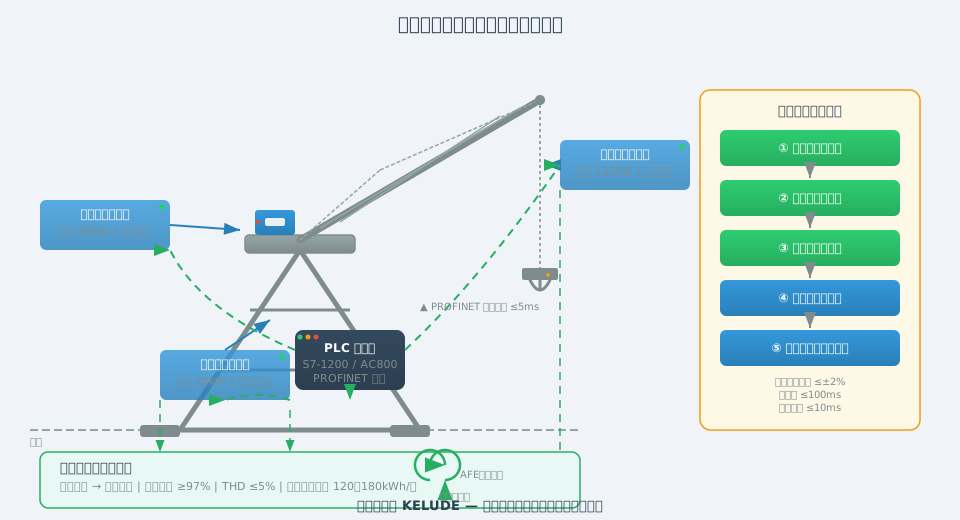
The quantitative targets for three-mechanism coordinated synchronization are: speed following error ≤ ±2% (i.e., deviation between commanded and actual feedback speed does not exceed 2%), acceleration time deviation between mechanisms ≤ 0.5 s, and total delay (from Control Grip input to VFD output response) ≤ 100 ms. Key factors affecting synchronization accuracy include: communication bus cycle time (≤ 10 ms), VFD speed loop response bandwidth (≥ 80 rad/s), and consistent matching of acceleration/deceleration time parameters.
Speed Control Parameter Matching
The first step in coordinated commissioning is matching the acceleration/deceleration time parameters of all three mechanisms so they start and stop in unison. Using a typical medium-sized gantry crane as an example: hoisting mechanism acceleration time 8 s (0 to rated speed 12 m/min), luffing mechanism acceleration time 10 s (0 to rated speed 30 m/min), slewing mechanism acceleration time 12 s (0 to rated speed 1.0 r/min). The Control Grip travel is mapped linearly to the speed command, and the ramp time parameters for all three VFDs must be identical to prevent any single mechanism from "lunging ahead" or "lagging behind."
Commissioning Procedure
Phase 1 — Single-Mechanism No-Load Testing: Commission each mechanism individually — hoisting, luffing, and slewing — covering VFD parameters, encoder direction, Brake application logic, limit switch protection, and acceleration/deceleration curves. Verify stability and smoothness at zero speed and in the low-speed range (0.5 Hz – 5 Hz).
Phase 2 — Single-Mechanism Load Testing: Load the hoisting mechanism to 50%, 75%, 100%, and 110% of rated load; measure Load slipping (≤ 3 mm), overspeed protection activation, and braking distance. Test luffing and slewing mechanisms at 50% and 100% rated load, monitoring boom attitude and load swing amplitude during acceleration and deceleration.
Phase 3 — Two-Mechanism Coordination: Hoisting + luffing interlock (raise boom while hoisting, lower boom while lowering), verifying resultant speed accuracy along diagonal load paths; hoisting + slewing interlock (hoist or lower during slewing), verifying height-holding accuracy along circular load paths.
Phase 4 — Three-Mechanism Coordinated Load Test: The operator simulates actual lifting conditions, simultaneously operating hoisting, luffing, and slewing to complete the full cycle: "hoist — inching/jog slewing — travel — luffing adjustment — precise positioning — lowering — landing." The PLC records speed feedback from each mechanism and bus communication delay, confirming speed following error ≤ ±2% and total delay ≤ 100 ms.
Phase 5 — Full-Load Reliability Verification: Run continuously for 2 hours at 110% rated load, monitoring VFD radiator temperature (temperature rise ≤ 40 K), DC bus voltage fluctuation (≤ ±5 VDC), and communication packet loss rate (≤ 0.01%), validating thermal stability and communication reliability under extreme operating conditions.
During coordinated commissioning, wireless safety monitoring devices (load indicator, anemometer, wire rope tension detection) must be in place to continuously monitor critical safety parameters and record them in the commissioning report. Upon completion, a full commissioning report for the gantry crane VFD retrofit is issued and archived for future reference.
PLC Network Integration and Remote Monitoring
After the VFD retrofit, the entire system is integrated into a centralized PLC control network, enabling unified operation, monitoring, diagnosis, and remote maintenance.
PLC Selection and Network Architecture: The main controller recommended is the Siemens S7-1200 or S7-1500 series (supporting PROFINET RT/IRT communication, scan cycle ≤ 50 ms); alternatively, the Mitsubishi FX5U (CC-Link IE Field) or Inovance AC800 series may be used. The three hoisting/luffing/slewing VFDs are connected to the PLC via a PROFINET network switch in a star topology, with a communication cycle set to 5–10 ms to ensure synchronized speed commands across all three mechanisms. The operator station uses a KTP700 series Touch Screen (HMI) (7-inch TFT) or KTP1200 (12-inch), connected to the PLC via PROFINET, providing status monitoring (VFD operating frequency, current, voltage, torque, temperature), fault alarm logging (last 100 historical alarms with timestamps), and online parameter adjustment.
Data Collection & Analysis: The PLC periodically collects the following data and writes it to a local database or uploads it to a server via MQTT/OPC UA protocols: cumulative operating hours per mechanism (for maintenance interval reminders), cumulative energy consumption (kWh, for energy benchmarking analysis), VFD alarm frequency statistics (to identify mechanisms prone to recurring faults), and Control Grip travel data (for operational compliance analysis). The collection cycle is ≤1 second, with data retention of at least 6 months.
Remote Monitoring Solution: An industrial IoT gateway (e.g., Siemens IoT2050, Advantech WISE-5000) is deployed on the PLC side, connecting via 4G/5G or the enterprise LAN to a Cloud Platform (supporting Alibaba Cloud IoT, AWS IoT, or private servers). The remote monitoring platform provides real-time operating status for each mechanism, historical operating curves (speed/current/temperature playback), automatically generated daily/weekly/monthly energy reports, fault alarm push notifications (via WeChat, SMS, or email), and remote backup and restoration of VFD parameters. In a shipyard project involving remote monitoring of three portal cranes, the average equipment fault Response time dropped from 4 hours to 30 minutes after the remote platform went live, with unplanned downtime reduced by approximately 35%.
Cybersecurity: Remote Monitoring access is established through a VPN encrypted tunnel into the enterprise intranet, with a firewall isolating the PLC from the host computer. Remote endpoints are prohibited from directly accessing the PLC core program. VFD commissioning ports (e.g., Siemens MMC card/USB) must be password-locked and sealed after commissioning to prevent unauthorized Parameter modifications.
