

Nuclear Power Plant Circular Crane Custom Design
Non-Standard Design of Nuclear Power Plant Polar Cranes: Seismic and Radiation Requirements Are Far Stricter Than You Think. Introduction Nuclear power plant polar cranes (also known as polar cranes) are the core lifting equipment inside the reactor building, installed on a circular rail beneath the containment dome. They handle critical tasks such as hoisting the reactor pressure vessel head, replacing steam generators, and installing and maintaining reactor internals. The rated lifting capacity of a polar crane is typically 205t or 360t, with a main hoisting height of approximately 40m, travel speed of 0.3–3.5m/min, and a rail diameter ranging from 37m to 44m. Unlike standard industrial cranes, nuclear power plant polar cranes are classified as safety-related structures, systems, and components (SSC). Their non-standard design must simultaneously satisfy four stringent requirements: seismic resistance, radiation protection, fail-safe operation, and nuclear-grade certification. The RCC-M Code (French rules for the design and construction of nuclear island equipment) and ASME NOG-1 (nuclear power plant crane standard) serve as the internationally recognized design bases, while ISO 4301 Crane Design Standard provides the fundamental calculation formulas. Kelude Heavy Industry has accumulated extensive engineering practice experience in the non-standard design of nuclear power plant polar cranes. The following analysis breaks down the core technical points across eight dimensions.
Seismic Design Analysis (SSE/OBE Criteria)
The seismic design of nuclear power plant polar cranes employs a dual-basis earthquake system: the Operating Basis Earthquake (OBE) corresponds to a peak ground acceleration of 0.1g, requiring the crane to retain full functionality after an OBE and continue operation without shutdown. The Safe Shutdown Earthquake (SSE) corresponds to a peak ground acceleration of 0.3–0.5g (determined by site-specific seismic conditions), requiring the crane to neither collapse nor drop loads during or after an SSE, ensuring an unobstructed safe shutdown path for the reactor. Seismic analysis primarily uses two methods: the response spectrum method and the time-history analysis method. The response spectrum method uses a standard response spectrum with a 5% damping ratio as input, performing multi-modal analysis on the crane structure (typically taking the first 20 modes), with modal responses combined using the SRSS or CQC method. The time-history analysis method requires selecting no fewer than three sets of actual seismic acceleration time-history records that match the site conditions, each with a duration of no less than 20 seconds, conducting nonlinear time-history integration, and taking the envelope of maximum responses as the design basis.
In terms of structural design, the stress ratio of critical structural members of the polar crane is controlled below 0.85 (per ASME NOG-1), meaning the working stress does not exceed 85% of the material's yield strength. The strength reduction coefficient for weld zones is taken as 0.65, with the allowable stress in weld areas limited to 65% of the base material. The main girder and end carriage adopt box-section designs with plate thicknesses of no less than 20mm. Critical joints use full-penetration welding and undergo 100% ultrasonic testing (UT). The crane rail support brackets are designed as Class I seismic items, with connecting bolts using Grade 10.9 high-strength bolts and preload applied at 110% of the GB/T 1228 standard value. Wind and snow loads are based on a 50-year return period, while the effects of containment temperature loads (ambient to 65°C cycling) on rail expansion are considered, with rail expansion joints spaced at 40m intervals.
The natural frequency of the polar crane structure is a critical parameter in seismic design. The first-order vertical natural frequency of the main girder must avoid the predominant earthquake frequency range (typically 1–10Hz), achieved by adjusting the cross-sectional stiffness and mass distribution of the main girder. Typical first-order vertical natural frequencies for polar crane main girders range from 3–5Hz, with horizontal frequencies at 1.5–3Hz, both outside the concentrated seismic energy band. For nonlinear response under SSE conditions, factors such as bolt slip and wheel-to-rail clearance impact must be considered, using ANSYS or ABAQUS finite element software for pushover analysis to verify the structure's plastic deformation capacity and ductility ratio under severe earthquakes. The ductility ratio of the steel structure is controlled within 4 to ensure post-earthquake repairability. Seismic calculations also include the dynamic interaction between the crane and the rail, with the wheel-to-rail friction coefficient taken as 0.15–0.20.
Radiation-Proof Sealing Solutions (Remote Control / Redundant Safety)
The radiation-proof sealing solution for nuclear power plant polar cranes covers four key technical dimensions: electrical component protection, enclosure sealing, remote control, and redundant safety. The core specifications are summarized in the data cards below.
Cumulative Dose: 1×10⁵Gy design life
Standard Industrial Grade: Only 1×10²–1×10³Gy
Difference: 2–3 orders of magnitude
Hardening Technique: Borated polyethylene shielding layer
Substrate: Specialty ceramic substrate
Test Standard: IEEE 323 radiation aging test
Test Dose: 1.5× design life total dose
Radiation-Resistant Cable: IEEE 383 low-smoke, halogen-free, flame-retardant
Post-Irradiation Insulation: ≥1×10⁶MΩ·km
Protection Rating (IP): IP66
Protective Gas: 99.99% purity nitrogen
Micro-Positive Pressure: 200–500Pa
Sealing Structure: Fully welded sealed enclosure
Seal: Silicone seal strip + labyrinth seal
Total Coating Thickness: ≥300μm
Surface Contact Angle: >90° (easy decontamination)
Third-Party Inspection: Protection rating confirmed by laboratory testing
Communication: All-digital fiber-optic redundant ring network
End-to-End Latency: ≤200ms
PLC Architecture: Dual-CPU hot standby (switchover ≤50ms)
Operator Console: Three 24-inch high-definition displays
Display Data: 3D positioning / load / radiation dose rate
Virtual Fence: Automatic deceleration to 50mm in 3D restricted zones
Camera Tolerance: 1×10⁴Gy CCD sensor
Lighting: LED auxiliary (fully operational in darkness)
Drive System: Independent VFD and braking for hoist, bridge, and trolley travel
Fault Tolerance: Emergency operation remains possible with any single drive system failure
Lifting Capacity Limiter: Accuracy ±1%
Hoisting Height Limiter: Dual-level redundancy
Interlock Signals: Hard-wired to dedicated safety PLC
Radiation Monitoring: Real-time dose rate probes
Alarm Threshold: Automatic audible and visual alarm above 2.5μSv/h
Fail-Safe Braking System
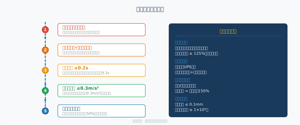
The braking system of the polar crane is a critical line of defense for nuclear safety. It is designed on the fail-safe principle, meaning any single fault—including a power loss—automatically triggers brake engagement, bringing the hoisting mechanism to a safe stop. Each hoisting mechanism is equipped with two fully independent brakes, available in disc or shoe configurations. The braking torque of a single brake is no less than 125% of the rated load torque. The control circuits of the two brakes are electrically isolated from each other—with independent power feeds (each supplied from a separate UPS power source), independent output relays, and independent contact feedback signals—so that after a single electrical or mechanical fault, the remaining brake can still complete a safe stop on its own. The brakes are of the fail-safe type (spring-applied, power-off release), with electromagnetic release and spring actuation. Brake response time does not exceed 0.2s. Under emergency braking conditions, the deceleration of the lifting load is limited to no more than 0.3m/s², preventing excessive impact that could damage the suspended load.
Brake condition is monitored in real time via proximity switches and wear sensors. An alarm is triggered automatically when brake lining wear exceeds 50% of the original thickness, with the replacement threshold set at 50% of initial thickness. Brake disc radial runout tolerance does not exceed 0.1mm, and face runout does not exceed 0.05mm. Brake springs are designed for a fatigue life of no less than 1×10⁶ cycles, with annual braking torque spot tests. In addition to the hoist brakes, the bridge and trolley travel mechanisms are also equipped with independent brakes, sized at 150% of the rated torque. All braking system signals are simultaneously transmitted to the main control room DCS for full life-cycle condition monitoring. During emergency braking, the braking distance is controlled to within the sliding distance corresponding to 0.5s at rated hoisting speed, while braking deceleration remains below 0.3m/s² to prevent excessive load swing.
Special Material Requirements
The material system of a nuclear power plant polar crane differs fundamentally from that of conventional cranes. For load-bearing structural steel, the main girder and end carriages are fabricated from low-alloy high-strength steel Q420FZ, with through-thickness performance grade Z35 (reduction of area no less than 35%), meeting the toughness requirements for pressure boundary materials specified in RCC-M Section M5132. When the design temperature falls below -20°C, materials must pass a -40°C impact toughness test (KV₂≥40J). Components inside the nuclear island that may come into contact with radioactive media are made of austenitic stainless steel 316L, with a nickel content of no less than 10%, chromium content of 16–18%, and molybdenum content of 2–3%, providing excellent resistance to irradiation embrittlement and stress corrosion cracking. The crane hook is forged from nuclear-grade alloy steel 34CrNiMo6, heat-treated to a minimum yield strength of 700MPa. The critical cross-section of the hook is designed with a safety factor of ≥5—while ISO 4301 Crane Design Standard specifies a factor of 3 for general-purpose cranes, the nuclear-grade requirement is raised to 5.
The wire rope is galvanized high-strength steel rope, with a construction of 6×36WS+IWR or 35×7 class, and a nominal tensile strength of 1770MPa or 1960MPa. The safety factor is increased from the 5:1 required for conventional cranes to 7:1. The ratio of sheave diameter to wire rope diameter is no less than 40 (compared to 25 for standard cranes). Wire rope terminations are secured by alloy socketing; wedge sockets are not permitted on nuclear-grade polar cranes. The protective coating system consists of a three-layer structure: epoxy zinc-rich primer (zinc content ≥80%), epoxy MIO intermediate coat, and polyurethane topcoat, with a total dry film thickness of no less than 300μm. The system must withstand a salt spray test of no less than 1,000 hours without blistering or rusting. All nuclear-grade materials must be accompanied by complete material test reports (MTRs), with chemical composition and mechanical properties traceable to the heat number.
The selection of nuclear-grade welding consumables is equally stringent. Electrodes are low-hydrogen basic type (e.g., E5015-G), dried at 350–400°C for 2 hours before use, and stored in insulated buckets for no more than 4 hours. Submerged arc welding wires are used with agglomerated fluxes, and the deposited metal must achieve an impact energy of no less than 47J at -40°C. Welding procedure qualification records (WPQRs) are performed in accordance with RCC-M Section S6000, with each welding method and each base material combination requiring individual qualification. Weld repair is limited to a maximum of two repair cycles; beyond that, the base material is rejected. All load-bearing welds must undergo visual inspection, magnetic particle testing (MT) or penetrant testing (PT) within 24 hours after welding, followed by radiographic (RT) or ultrasonic (UT) examination, with the inspection ratio escalating from 25% to 100% depending on the safety level.
Nuclear Standard Comparison: RCC-M vs. ASME vs. GB/T
The design of a nuclear power plant polar crane must simultaneously satisfy the certification requirements of multiple standard systems. RCC-M (French nuclear island equipment design and construction rules), ASME NOG-1 (American nuclear crane standard), and ISO 4301/GB/T 4329 (Chinese national standards) each have their own focus in terms of application scope, certification procedures, and design criteria. The following cross-comparison examines key dimensions to provide a reference for standard selection in nuclear-grade polar crane design.
Kelude Heavy Industry: Overhead Crane & Gantry Crane Manufacturer
Kelude Heavy Industry is a professional manufacturer of overhead cranes, gantry cranes, and electric hoists. With over 20 years of experience in the material handling industry, we provide reliable lifting solutions for workshops, warehouses, steel plants, and other industrial facilities.
Domestic Substitution Solutions for Nuclear Polar Cranes
As China accelerates the localization of nuclear power equipment, significant progress has been made in substituting key polar crane components with domestically manufactured alternatives. For structural steel, the domestic low-alloy steel Q420FZ is now available in volume, with chemical composition (C≤0.20%, Si≤0.55%, Mn≤1.70%, P≤0.020%, S≤0.010%) and mechanical properties (Yield Strength ≥420MPa, Tensile Strength 550–720MPa, impact energy ≥47J at -40°C) fully equivalent to European standard S355J2+N. This material can replace imported steel for Main Girder and End Carriage fabrication. Domestic nuclear-grade cables (e.g., products from Anhui Cable and Changzhou Bayi Cable) have passed the IEEE 383 irradiation aging test, withstanding radiation doses up to 1×10⁵Gy.
For nuclear-grade motors, the domestic YJK series asynchronous motors (power range 15–315kW) have obtained K3 nuclear certification. Their insulation system uses Class H construction (Temperature Resistance 180°C), with radiation tolerance of no less than 5×10⁵Gy and a minimum of 1×10⁴ starts over the service life. In terms of reducers, domestically produced nuclear-specific Planetary Reducers (e.g., from NGC and Chongchi) achieve ISO 6336 Gear load capacity calculation standard Grade 5 accuracy, with efficiency of no less than 96% and a 40-year design life. The overall localization rate has risen from below 50% in 2010 to over 85% today, with comprehensive costs 20%–30% lower than imported solutions and delivery lead times reduced from 24 months to 14–18 months. Kelude Heavy Industry has successfully implemented fully localized polar crane solutions across multiple nuclear power projects, with equipment performance and reliability verified through engineering practice to match international standards.
In the nuclear certification process, the National Nuclear Safety Administration enforces a three-stage review system for domestic polar cranes: "Design Confirmation + Type Test + First-Unit Verification." The design confirmation stage reviews seismic calculation reports and stress analysis documentation; the Type Test stage witnesses all nuclear-specific tests; and the first-unit verification stage conducts a Static load test at 125% of rated load and a Dynamic Load Test at 110% of rated load on-site, along with emergency braking distance measurements (not exceeding the sliding distance corresponding to Lifting Speed × 0.5s). The Mean Time Between Failures (MTBF) reliability indicator for domestic polar cranes has improved from 2,000 hours in the early stages to over 8,000 hours, approaching the 10,000-hour level of imported equipment. For Controllers and Variable Frequency Drives (VFDs), nuclear-specific products from domestic brands such as Inovance and INVT are now in the nuclear certification pipeline, with the localization rate expected to exceed 95% within the next 3–5 years.
