

Crane Welding Robot Line Precision Control
Crane Manufacturing Process: Precision Control in Robotic Welding Lines. In crane manufacturing, weld quality directly determines structural strength, fatigue life, and operational safety of the equipment.
In crane manufacturing, weld quality is the decisive factor for structural strength, fatigue life, and operational safety. Kelude Heavy Industry, a leading crane manufacturer in China, has in recent years pushed forward a comprehensive digitalization and automation retrofit of its welding operations, establishing robotic welding production lines that cover core components such as main girders, end carriages, and trolley frames. By integrating industrial robot technology with welding process engineering, Kelude has achieved end-to-end digital control spanning pre-weld assembly, the welding process itself, and post-weld inspection. The first-pass weld acceptance rate exceeds 98.5%, with weld seam quality meeting the highest grade requirements of national standards including GB/T 19869.1 (Welding procedure qualification record), GB/T 11345-2013 (Non-destructive testing of welds — Ultrasonic testing), and GB/T 3323 (Non-destructive testing of welds — Radiographic testing). This article systematically examines Kelude's technical practices in crane welding automation across five dimensions: welding method selection, robotic line layout, process parameter optimization, assembly accuracy control, and online weld quality detection.
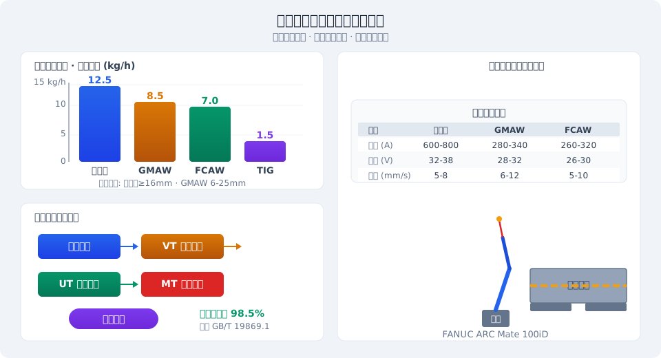
Crane Weld Structure Classification and Welding Methods
The metal structure of a crane is primarily composed of welded structural components including main girders, end carriages, trolley frames, outriggers, and cross beams. Each component type presents distinct weld seam configurations, load conditions, and welding requirements. Kelude Heavy Industry selects differentiated welding methods for each component and weld seam type to strike the optimal balance among welding efficiency, quality, and cost. The table below summarizes the welding method selection for major crane structural components.
| Structural Component Type | Primary Weld Seam Structural Component Type | Recommended Welding Method | Welding Material | Applicable Plate Thickness(mm) | Welding Position |
|---|---|---|---|---|---|
| Main Girder(Box Girder) | Upper/Lower Flange and Web plate Fillet weld | Submerged Arc Welding(SAW) | H08A+HJ431 | 6~40 | Fillet Weld in Flat Position (Gravity Position) |
| Main Girder(Box Girder) | Stiffener / Stiffening Rib Lower Flange and Web plate Fillet weld | Gas-Shielded Welding(GMAW) | ER50-6/CO₂ | 4~20 | Vertical Welding/Flat Welding |
| End Carriage | Web plate Lower Flange and Flange plate Butt Weld | flux-cored wire Arc Welding(FCAW) | E71T-1 | 8~25 | Flat Welding/Horizontal Welding |
| Trolley Frame | Stiffener Plate and Base Plate Fillet weld | Gas-Shielded Welding(GMAW) | ER50-6/Ar+CO₂ | 5~20 | Flat Welding/Overhead Welding |
| Outrigger(Gantry Crane) | Main Weld Seamand Reinforcement Plate Weld Seam | Submerged Arc Welding(SAW)+ Gas-Shielded Welding(GMAW) | H08MnA+HJ431/ER50-6 | 10~50 | Flat Welding |
| Rail Clamp / Rail Clipand Connector | Small Size Fillet weld | flux-cored wire Arc Welding(FCAW) | E71T-GS | 3~12 | All-Position |
Kelude Heavy Industry's welding method selection follows the requirements of GB/T 19869.1 for welding procedure qualification. Every welding method must undergo procedure qualification testing before it can be used in batch production. For newly developed welding parameter combinations, mechanical property tests (tensile, bending, impact) and macroscopic metallographic examination are also required to ensure that the mechanical properties of welded joints are not lower than those of the base metal.
Welding Robot Production Line Layout
Kelude Heavy Industry's welding robot production line adopts a flexible, cell-based layout. Different types of welding robot workstations are configured according to the dimensions of crane structural components and their welding process characteristics. Taking the main girder welding line as an example, the line consists of the following workstations:
Pre-weld assembly workstation — Uses 3D laser scanning and Digital Twin technology to perform in-line inspection of assembly gaps and misalignment between the main girder web plate and flange plate. Assembly accuracy is controlled within ±1.0 mm.
Gantry welding robot workstation — Equipped with two FANUC M-710iC/50 welding robots, each with a 50 kg payload and 2050 mm working radius, paired with a 5 m × 3 m welding positioner to achieve ship-position welding of the four longitudinal seams of the main girder.
Stiffener welding robot workstation — Equipped with two KUKA KR16 welding robots with laser vision seam tracking to automatically complete multiple fillet welds between stiffeners and the web plate.
End carriage welding workstation — Equipped with an ABB IRB2600 welding robot to complete butt and fillet welds on end carriages.
Trolley frame welding workstation — Equipped with a six-axis collaborative robot to handle the complex spatial weld seams of trolley frames.
Workpieces are transferred between workstations by AGVs (Automated Guided Vehicles) and RGVs (Rail Guided Vehicles). The line control system interfaces with the MES (Manufacturing Execution System) for automatic production task dispatch and real-time welding data collection. The overall automation rate of Kelude Heavy Industry's welding robot production line exceeds 85%, and single-shift production capacity is 3 to 5 times higher than traditional manual welding.
Welding Parameter Optimization
Welding parameters are the core factors determining weld quality and welding efficiency. Kelude Heavy Industry has established a welding parameter optimization platform based on Response Surface Methodology (RSM) and Genetic Algorithm (GA), covering key parameters including welding current (I), arc voltage (U), welding speed (v), electrode stick-out (ESO), and shielding gas flow rate (Q).
Taking Submerged Arc Welding of the main girder flange-to-web joint as an example, the optimized parameter window is: welding current 550–650 A (DC reverse polarity), arc voltage 32–36 V, welding speed 35–45 cm/min, wire diameter 4.0 mm, electrode stick-out 25–35 mm, and flux layer thickness 30–40 mm. Within this parameter window, the weld bead form factor (weld width / weld penetration) remains stable at 1.2–1.6, the macroscopic metallographic structure consists of fine acicular ferrite plus proeutectoid ferrite, weld hardness is controlled within HV220–280, and heat input is maintained at 1.2–1.8 kJ/mm.
For Gas-Shielded Welding (GMAW), Kelude Heavy Industry has independently developed a double-pulse welding process — low-frequency pulses (1–3 Hz) control molten pool oscillation to improve fusion, while high-frequency pulses (100–200 Hz) control droplet transfer for stable spray transfer. This effectively resolves burn-through and spatter issues in thin-plate welding. Any change to welding parameters must be validated through procedure qualification in accordance with GB/T 19869.1, and a formal WPS must be issued before the parameters can be applied to batch production.
Pre-Weld Assembly Accuracy Control
Pre-weld assembly accuracy is a critical factor affecting weld quality and welding distortion. Kelude Heavy Industry has established a three-pronged pre-weld assembly accuracy control system:
Cutting accuracy control — Steel plates are cut using fine plasma or laser cutting. Cut surface perpendicularity deviation is ≤0.5°, cutting dimensional tolerances meet GB/T 1804-m requirements, and groove angle tolerance is ±2.5°.
Fit-up assembly accuracy control — A 3D laser scanner performs in-line inspection of the web plate and flange plate. Assembly gaps are controlled within 0–2.0 mm (for plate thickness ≤20 mm) or 0–2.5 mm (for plate thickness >20 mm). Edge misalignment is controlled within 0.5 mm (for plate thickness ≤20 mm) or 1.0 mm (for plate thickness >20 mm). Out-of-tolerance parts must be reworked manually or scrapped.
Tack weld accuracy control — Robotic automatic tack welding replaces manual tack welding. Tack weld length is 30–50 mm with 300–500 mm spacing, and the cross-section of tack welds is approximately one-third to one-half of the final weld, ensuring that assembly dimensions do not shift during subsequent automatic welding due to insufficient tack weld strength.
Kelude Heavy Industry's pre-weld assembly accuracy control system is integrated with the MES. Inspection data from each process step is automatically uploaded to the quality traceability database, enabling full-element quality tracing from cutting to final delivery. Thanks to strict assembly accuracy control, the first-pass acceptance rate for main girder welding remains stable at over 98%, with a rework rate below 2% — far better than the industry average.
In-Line Weld Quality Inspection
In-line weld quality inspection is a key quality assurance step in the welding robot production line. Kelude Heavy Industry has integrated multiple in-line inspection technologies into the line:
Welding process monitoring system — Real-time monitoring of welding current, arc voltage, wire feed speed, and welding speed, compared against the standard parameter window. When parameter deviation exceeds the set threshold, an alarm is triggered and deviation data is recorded as reference for weld quality assessment.
Laser vision seam tracking and profile inspection system — A laser vision sensor integrated at the front of the robot torch tracks the groove position in real time (tracking accuracy ±0.2 mm), while laser stripes measure the weld reinforcement, bead width, and undercut profile after welding.
Weld surface defect vision inspection system — High-resolution industrial cameras and AI image recognition algorithms perform 100% in-line inspection of weld surfaces. The detection rate for defects such as porosity, slag inclusion, cracks, undercut, and weld buildup exceeds 95%.
For welds flagged as suspected defects by in-line inspection, Kelude Heavy Industry performs ultrasonic testing (UT) in accordance with GB/T 11345 requirements for non-destructive testing of welds, with radiographic testing (RT) per GB/T 3323 used for confirmation when necessary. All in-line inspection data is linked to the weld ID (QR code label) and stored in Kelude Heavy Industry's quality big data platform, creating a complete quality data archive from welding process parameters to final inspection results.
Welding Distortion Control and Correction
Welding distortion is an unavoidable quality issue in crane manufacturing that directly affects structural dimensional accuracy and assembly quality. Kelude Heavy Industry has established a systematic welding distortion control system based on the principle of "prevention first, correction second."
At the prevention level, the following measures are adopted:
Optimized welding sequence — Main girder welding proceeds from the center toward both ends, with flange-first, web-second symmetrical welding to distribute heat input evenly and reduce overall bending and angular distortion.
Controlled heat input — Low-heat-input welding processes are preferred wherever weld quality permits, keeping heat input within 1.0–1.8 kJ/mm to reduce shrinkage in the heat-affected zone.
Pre-set counter-deformation — Based on finite element welding distortion simulation and long-term data accumulation, counter-deformation allowances are pre-set for key structural components such as main girders and end carriages (longitudinal shrinkage allowance of 0.5–1.0 mm per meter and transverse shrinkage allowance of 0.3–0.8 mm per meter), ensuring post-weld dimensions fall within tolerance.
At the correction level, Kelude Heavy Industry uses two methods: Flame straightening — Heating along the weld line on the reverse side of the weld (heating temperature 600–800°C) to correct angular and bending distortion through thermal contraction; and mechanical straightening — Cold correction using hydraulic straightening machines and press machines, suitable for local distortion correction on plates thinner than 20 mm.
Kelude Heavy Industry's welding distortion control system keeps main girder post-weld straightness deviation within ≤L/2000 (L = girder length) and end carriage diagonal difference within ≤5.0 mm — well within the accuracy requirements of ISO 4301.
Frequently Asked Questions
Further reading: Full-Machine Load and Reliability Tests on Three Test Platforms | From Simulation to Mass Production: Engineering Execution Explained
