

Overhead Crane AI Vision Safety: Intrusion & Anti-Collision
AI-Powered Visual Safety Monitoring for Overhead Cranes: Personnel Intrusion Detection and Anti-Collision in Lifting Operations. The AI visual safety monitoring system for overhead cranes serves as the final active defense layer in crane safety protection. It uses industrial AI cameras mounted on the end carriages and main girder to capture real-time images of the lifting zone. Powered by the YOLOv8 deep learning model, the system detects personnel intrusion beneath and around the suspended load. When a person enters the hazardous area, the system automatically triggers a deceleration warning or STO safe stop, upgrading the physical separation between workers and loads from passive barriers to active intelligent protection.
The AI visual safety monitoring system for overhead cranes is the last line of active defense in intelligent crane safety. Industrial AI cameras installed on the end carriages and main girder capture real-time footage of the lifting zone at 30 fps. The YOLOv8 deep learning model detects personnel intrusion beneath and around the suspended load, automatically triggering deceleration warnings or STO safe stops the moment a person enters the hazardous area. This transforms the physical separation between workers and loads from passive guardrails into active, intelligent protection. Kelude Heavy Industry has built a complete AI safety monitoring system—covering detection, tiered alarms, and anti-collision interlocking—on the NVIDIA Jetson Orin NX edge computing platform with a proprietary vision detection model. This article walks through the full engineering practice, from system architecture and model training to on-site deployment.
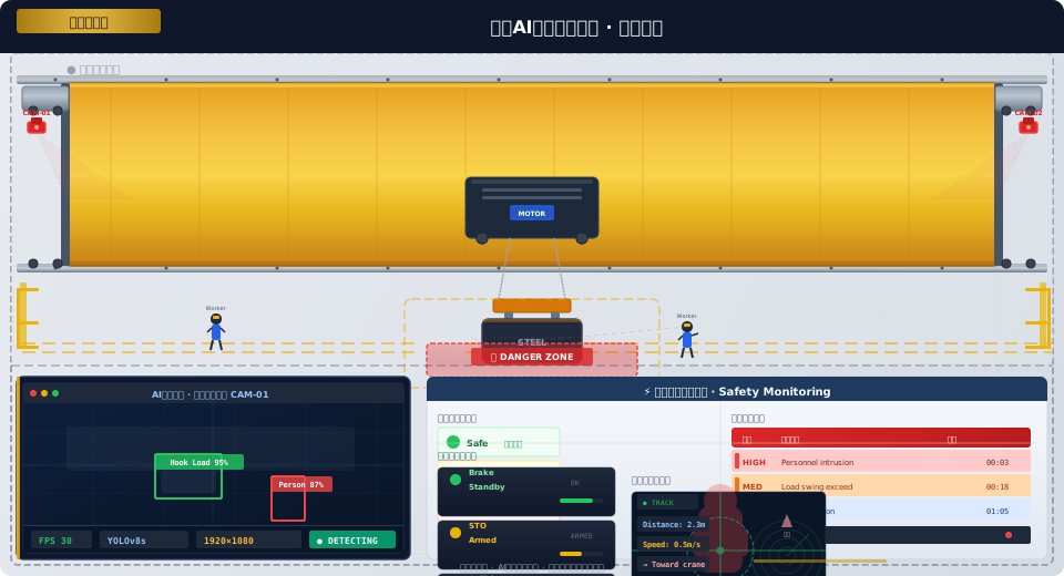
AI Vision Safety System Architecture for Overhead Cranes
The AI visual safety monitoring system for overhead cranes is built on a four-layer architecture: perception, inference, control, and alarm. The perception layer consists of 2–4 industrial AI cameras—mounted on both sides of the end carriages and beneath the trolley—capturing 1080P real-time images of the lifting zone at 30 fps and transmitting them to the inference layer over Gigabit Ethernet. The inference layer runs on the NVIDIA Jetson Orin NX edge computing module (100 TOPS), executing the YOLOv8s object detection model to identify personnel, loads, and obstacles in each frame with a single-frame inference latency of under 15 ms. The control layer connects to the crane PLC via GPIO and PROFINET interfaces—when personnel intrusion is detected, it sends deceleration or stop signals to the PLC, which executes SLS deceleration or STO stop. The alarm layer includes an Audible & Visual Alarm (buzzer + rotating warning light) in the operator's cab, HMI pop-up alerts, and real-time alarm push notifications on the remote operation and maintenance platform. The system's end-to-end latency—from the moment a person enters the hazardous area to the PLC executing the safety action—is under 100 ms, meeting the response time requirements for active safety protection specified in GB/T 28264-2017 Safety Monitoring and Management System for Lifting Appliances.
The detection zone is divided into three safety tiers. The Danger Zone is a circular area with a 3 m radius centered on the suspended load—personnel entering this zone immediately triggers an STO stop, with the overhead crane brake engaging within 200 ms. The Warning Zone is the annular area extending from 3 m to 6 m beyond the danger zone—personnel entering this zone triggers the audible and visual alarm and crane deceleration (speed reduced to 20% of rated speed), with the deceleration signal sustained until the person leaves the warning zone. The Monitor Zone is the annular area extending from 6 m to 10 m beyond the warning zone—personnel entering this zone is only logged in the event history without control intervention, providing data for analyzing personnel activity frequency and patterns in the lifting zone. The radius parameters of all three safety zones can be adjusted on-site via the HMI panel based on crane capacity and load dimensions.
Camera Selection and Installation for Crane Safety Monitoring
Camera selection and mounting position directly determine detection performance. Kelude Heavy Industry equips the AI visual safety monitoring system with two standard camera configurations: for end carriage mounting, the Hikvision DS-2CD2T87WD-L (8 MP starlight-grade, 1/1.2-inch sensor, minimum illumination 0.001 Lux, IR range up to 50 m); for trolley underside mounting, the Imaging Source DMK 33GX290 (1.9 MP global shutter, 1/3-inch sensor, 120 fps frame rate, ideal for tracking high-speed moving loads and personnel). The end carriage camera uses a 6 mm lens (approximately 52° horizontal field of view), mounted at the center of the end carriage's underside, pointing vertically downward to cover the entire lifting zone beneath the crane. The trolley camera uses a 3.6 mm lens (approximately 87° horizontal field of view), mounted on the underside of the trolley platform to capture the close-range area directly beneath the lifting spreader.
| Mounting Position | Camera Model | Parameter | Coverage Area | Function |
|---|---|---|---|---|
| End Carriage(Left) | DS-2CD2T87WD-L | 8,000,000/0.001Lux/6mm | Left Lifting Zone+Aisle | personnel intrusion detection |
| End Carriage(Right) | DS-2CD2T87WD-L | 8,000,000/0.001Lux/6mm | Right Lifting Zone+Aisle | personnel intrusion detection |
| Trolley Below | DMK 33GX290 | 1,900,000/Global Shutter/3.6mm | Lifting spreader Near Field Below | Load Sway/Obstacle Detection |
| Main Girder Above | DS-2CD2T87WD-L | 8,000,000/0.001Lux/12mm | Full Workshop Long Range | Global Situational Awareness(Optional) |
The camera mounting structure uses a stainless steel universal adjustment bracket (support arm rated for 15 kg, capable of withstanding impact loads during crane start/stop cycles). The camera connects via CAT6A shielded cable to the Jetson Orin NX edge computing module housed in the control cabinet. The cable runs along the inside of the crane main girder, secured with cable ties, and maintains a minimum clearance of 300 mm from the VFD power cables. Camera power is supplied via PoE+ (802.3at standard, 25 W per port), with the Jetson module powering the camera through the network switch's PoE+ ports—no separate power wiring required.
YOLOv8 Object Detection Model Training and Deployment
YOLOv8 is the core algorithm powering Kelude's AI vision detection for overhead cranes. For crane safety monitoring, Kelude selected the YOLOv8s variant (Small, 11.2M parameters, 44.9% COCO mAP). After TensorRT FP16 optimization on the NVIDIA Jetson Orin NX, inference speed reaches 60 fps at 640x640 input resolution—well above the 30 fps requirement for real-time video stream analysis. The training dataset draws from three sources: annotated images from Kelude's own crane test facility (approximately 15,000 images covering varied lighting, weather, and load types), synthetic images for long-tail scenarios (approximately 5,000 images simulating falls, crowd gathering, partial occlusion, and other edge cases), and supplementary workshop captures (approximately 3,000 images providing diverse backgrounds across different factory layouts and production line configurations).
Training configuration. The model was trained on the Ultralytics YOLOv8 framework with 640x640 input resolution, batch size of 32, and 300 training epochs. Data augmentation included Mosaic (probability 0.8, 4-image stitching), MixUp (probability 0.2, 2-image blending), HSV augmentation (H±25°/S±30%/V±30%), and random rotation (±10°). Training ran on a single NVIDIA RTX 4090 (24 GB VRAM), with each epoch taking approximately 10 minutes—roughly 50 hours total for 300 epochs. The trained model was exported as a TensorRT FP16 engine file (approximately 22 MB) and deployed to the Jetson Orin NX.
Detection target classes. The YOLOv8s model outputs three detection classes. Each detection box includes a class ID, confidence score (threshold ≥ 0.5 retained), and normalized box coordinates (cx, cy, w, h). Box coordinates are mapped to the ground-plane world coordinate system via a perspective transformation matrix, achieving positioning accuracy within 10 cm deviation. The three target classes are detailed below:
Personnel Intrusion Detection Algorithm and Safety Zone Logic
The personnel intrusion detection sequence is executed as follows. Step 1 – Object detection: The Jetson module runs the YOLOv8s model and outputs all person bounding boxes in the current frame. Step 2 – Coordinate mapping: The bottom-center point of each person bounding box is mapped to the ground-plane world coordinate system using a perspective transformation matrix, yielding the person's physical position (x, y, in meters) on the workshop floor. Step 3 – Distance calculation: The Euclidean distance is calculated between the person's position and the load position (derived from the overhead crane PLC's absolute crane bridge position + absolute trolley position + load dimension offset). Step 4 – Safety zone evaluation: The distance is matched against a three-tier safety zone rule — dist ≤ 3m triggers STO in the Danger zone; 3m < dist ≤ 6m triggers deceleration and an alarm in the Warning zone; 6m 10m results in no action. Step 5 – Output: The Jetson outputs three alarm signals via GPIO — GPIO1 (Danger) connects to the PLC's safety DI input, GPIO2 (Warning) connects to the PLC's standard DI input, and GPIO3 (Monitor) connects to the IO-Link gateway for event logging.
Dynamic adjustment of the safety zone radius. The actual dimensions of the suspended load and its travel path affect the danger zone radius. When the load dimension is less than 1m, the danger zone radius remains at the default 3m; for loads between 1m and 3m, the radius increases automatically based on the load's diagonal length (R_danger = 3.0m + L_diag/2); for loads larger than 3m, the radius is fixed at 5m to prevent an oversized safety zone from triggering STO too frequently and reducing production efficiency. The current safety zone radius is displayed in real time on the HMI safety monitoring page, and operators can manually fine-tune it in 0.5m increments. All modifications to safety zone parameters are recorded in the PLC's event log with a retention period of no less than 90 days.
Multi-target tracking and debounce handling. When multiple persons are detected in a single frame, the system assigns a unique Track ID to each target and uses a lightweight DeepSORT algorithm for cross-frame target matching and trajectory tracking. A person is only confirmed to have entered a safety zone — and an alarm triggered — when the same Track ID appears at the same position for more than 5 consecutive frames, preventing false alarms caused by single-frame misdetections. While a person remains inside a safety zone, the alarm persists; once the person leaves the zone, the alarm is automatically cleared (with a 2-second debounce delay). Continuous alarm events are automatically recorded in a local SQLite database, with each record containing a timestamp, Track ID, person coordinates, triggered safety zone grade, and crane operating status (speed/position/direction).
Anti-Collision Interlock Control and STO Triggering
The vision inspection system and the crane safety control system are interlocked through a dual GPIO + PROFINET interface. The GPIO interface handles rapid braking in emergency scenarios — the Jetson's GPIO1 (Danger) is wired directly to the input channel of the PLC's safety F-DI module; when GPIO1 is pulled high to 24V, the PLC triggers STO within the next safety scan cycle (20ms). The PROFINET interface handles graded deceleration in non-emergency scenarios — the Jetson acts as a PROFINET IO device (GSDML file imported into TIA Portal for configuration) and periodically writes deceleration requests (including deceleration grade 0–3 and target speed percentage) to the PLC, which responds within a standard IO cycle (10ms).
| safety level | Trigger Condition | Control Braking Operation | Response time | Recovery Mode |
|---|---|---|---|---|
| Level 3 Danger | Personnel Entry≤3mDanger Zone | STOEmergency Stop | <100ms | Manual Reset Acknowledge |
| Level 2 Warning | Personnel Entry3~6mWarning Zone | Reduce Speed To20%+Audible and Visual Alarm | <200ms | Auto Resume After Personnel Exit |
| Level 1 Detection | Personnel Entry6~10mDetection Left Lifting Zone | Log Only | — | Automatic |
Recovery procedure after an STO event. When a Level 3 STO is triggered, the overhead crane stops immediately. The Jetson system continuously monitors the danger zone—once the zone is confirmed clear of personnel, it sends a "danger cleared" signal to the PLC via PROFINET. Upon receiving this signal, the PLC displays a safety reset confirmation dialog on the HMI, requiring the operator to visually verify that the lifting area is safe and then click the "Confirm Reset" button. Only then does the PLC release the STO state and permit re-enabling of operation. The complete STO event log is automatically uploaded to the edge gateway and pushed to the safety management system via OPC UA for archival.
System Commissioning and On-Site Validation
Commissioning of the AI visual safety monitoring system follows a four-step process. Step 1: Camera calibration. A checkerboard calibration target (12×9 grid, 30mm square size) is photographed from 15–20 different angles. The OpenCV calibrateCamera function is then used to compute the camera intrinsic matrix and distortion coefficients. After intrinsic calibration, the perspective transformation matrix is calibrated: a calibration mat (4×3m grid, 500mm grid spacing) is laid on the workshop floor, and a top-down image is captured. Four corner points and four corresponding points with known ground-plane coordinates are selected to compute the perspective transformation matrix. Following calibration, a Laser Distance Sensor is used to measure the actual coordinates of arbitrary points on the floor, verifying that the mapping error is less than 10cm.
Step 2: Model acceptance testing. Test scenarios (suspended load + mannequin) are set up at the test site. Detection accuracy is evaluated under four conditions: normal lighting (500 Lux), low light (50 Lux, infrared fill only), backlighting, and rain/fog (simulated spray). Acceptance Standard: person detection mAP ≥95% under normal lighting, ≥90% in low light, ≥85% under backlighting, and ≥80% in rain/fog. Each of the three safety-zone intrusion tests is performed 20 times, with the following pass criteria: Level 3 danger zone trigger rate 100% (20/20 STO activations), Level 2 warning zone trigger rate ≥95% (≥19/20 deceleration alarms), and Level 1 monitoring zone recording rate 100% (20/20 event log entries).
Step 3: On-site deployment verification. The calibration parameters and model are deployed to the Jetson module on the overhead crane. The safety monitoring page on the HMI displays real-time camera feeds with detection bounding-box overlays. The end-carriage cameras and trolley-mounted camera are verified for blind-spot-free top-down coverage at three crane positions (left end, center, and right end of the full travel range). The stitched view from the side cameras covers the entire lifting area beneath the crane (approximately 20m × 6m). Two-way radios are used to coordinate personnel walking along the safety-zone boundaries, verifying consistent alarm triggering at every boundary point. Step 4: Live operation. The system enters a 24-hour trial run. False-positive and missed-detection rates are checked from the detection logs every 8 hours, with acceptance criteria of ≤5 false positives per 24 hours and ≤1 missed detection per 24 hours. Upon successful completion of the trial, the system transitions to full operational status.
