

Overhead Crane Hoisting Mechanism Design & Selection Guide
Overhead Crane Hoisting Mechanism Design & Component Selection Guide: Drum, Gearbox, Brake, and Coupling Sizing. The hoisting mechanism is the most critical working assembly of an overhead crane — its design quality and component selection directly determine lifting capacity, operational safety, and service life.
The hoisting mechanism is the most vital working assembly of an overhead crane. Its design integrity and component selection directly affect the crane's lifting capacity, operational safety, and overall service life. The mechanism comprises six core components: the drive motor, gearbox (reducer), drum, brake, coupling, and wire rope — all of which must be precisely matched to deliver optimal performance. This article provides a systematic engineering reference for mechanical design engineers, detailing the design calculations and selection criteria for the four key components — drum, gearbox, brake, and coupling — in accordance with ISO 4301 Crane Design Standard and FEM 1.001 General Purpose Bridge Crane standard.
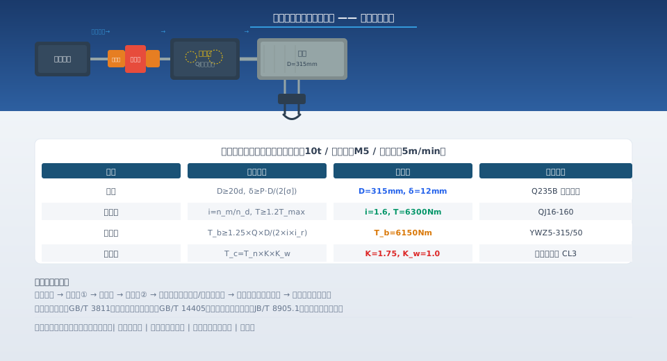
Drum Design and Sizing Calculations
The drum is the component that carries and spools the wire rope in the hoisting mechanism. Its design parameters directly influence wire rope service life and the overall compactness of the hoist.
Drum diameter calculation. The drum diameter D is determined as a multiple of the wire rope diameter d. Per ISO 4301: for bridge and gantry cranes with work duty classifications M3 to M5, D ≥ 20d; for classifications M6 to M7, D ≥ 25d. For example, a 10t crane with a 14mm hoist wire rope (work duty M5) requires D ≥ 20 × 14 = 280mm, rounded up to a standard diameter of 315mm. Increasing the drum diameter reduces bending stress on the wire rope and extends its lifespan, but it also raises the output torque requirement on the gearbox and increases the hoist's spatial footprint.
Drum wall thickness calculation. The drum wall thickness δ is governed by the radial pressure exerted by the wire rope on the drum shell. Per the formula recommended in ISO 4301: δ ≥ P × D / (2[σ]), where P is the maximum wire rope tension, D is the drum diameter, and [σ] is the allowable stress of the drum material (160 MPa for Q235B). A layer-pressure coefficient must be applied for multi-layer spooling: 1.0 for a single layer (n=1), 1.4 for two layers (n=2), and 1.8 for three layers (n=3). Drum materials are typically Q235B or Q355B seamless steel pipe or rolled-and-welded steel plate, with a wall thickness no less than 0.8 times the wire rope diameter. The rope guard plates at both drum ends must extend at least 2.5 times the wire rope diameter above the outermost layer to prevent wire rope derailment.
Rope capacity calculation. The drum's rope capacity L must exceed the product of the lifting height H and the pulley ratio i: L ≥ H × i + 3 wraps (safety wraps). Safety wraps refer to the number of rope turns that must remain on the drum at all times — even when the hook is at its lowest position, no fewer than 3 wraps must remain spooled on the drum. For a single-purchase hoist with a 10m lifting height, L ≥ 10 × 1 + 3 = 13m; for a double-purchase arrangement, L ≥ 10 × 2 + 3 = 23m. The drum groove radius is typically R = (0.53–0.56)d, groove depth h ≥ 0.35d, and groove pitch p = d + (2–4)mm.
| crane Specification | wire rope diameter | drum diameter | Wall Thickness | Rope Capacity |
|---|---|---|---|---|
| 5t | 11mm | 250mm | 10mm | 18m |
| 10t | 14mm | 315mm | 12mm | 25m |
| 20t | 18mm | 400mm | 16mm | 35m |
| 50t | 26mm | 600mm | 22mm | 60m |
Gearbox Selection and Verification
The gearbox converts the motor's high-speed, low-torque output into the low-speed, high-torque input required by the drum, making it the core component for speed and torque matching in the hoisting mechanism.
Determining the gear ratio. The total gearbox ratio i is determined by the motor's rated speed nm and the required drum speed nd: i = nm / nd. The drum speed nd is calculated from the lifting speed v and the wire rope pulley ratio ir: nd = 60 × v × ir / (π × D). For a 10 t crane as an example: lifting speed v = 5 m/min, pulley ratio ir = 2, drum diameter D = 0.315 m, giving nd = 60 × 5 × 2 / (π × 0.315) ≈ 606 r/min. With a motor speed nm = 960 r/min, the required ratio is i = 960 / 606 ≈ 1.58, so a standard gearbox with a ratio of 1.6 is selected.
Load capacity verification. The gearbox's load capacity is governed by the maximum working torque of the hoisting mechanism: Tmax = Q × D / (2 × i × ir × η), where Q is the rated lifting capacity (N), D is the drum diameter, i is the gearbox ratio, ir is the wire rope pulley ratio, and η is the overall efficiency of the hoisting mechanism (including gearbox, drum, and pulley block efficiencies, typically between 0.85 and 0.92). The gearbox's rated output torque must not be less than 1.2 to 1.5 times Tmax. Radial load must also be checked during gearbox selection: the radial force on the gearbox output shaft, generated by the drum's dead weight and wire rope tension, must not exceed the gearbox's allowable radial load. Common hoisting gearbox types include the ZQ series cylindrical gear reducers, QJ series crane-specific reducers, and planetary gear reducers. The QJ series is the industry-standard reducer for cranes, with mounting dimensions and load capacities specifically designed for hoisting duty.
Brake Selection and Braking Torque Calculation
The hoisting brake is the most critical safety component on a crane. It must reliably hold the rated load whenever the motor is de-energized.
Braking torque calculation. The braking torque Tb for the hoisting mechanism must be at least 1.25 times the working torque produced by the rated load on the drum (for the safety brake) and 1.5 times for the service brake, in accordance with the ISO 4301 Crane Design Standard. The formula is: Tb ≥ 1.25 × Q × D / (2 × i × ir) × K, where K is the brake mounting position factor (K = 1 when the brake is on the high-speed shaft, and K = i when on the low-speed shaft). In practice, the brake is typically mounted on the high-speed shaft between the motor and the gearbox, so K = 1 and Tb = (1.25–1.5) × Q × D / (2 × i × ir). For a 10 t crane (Q = 100 kN, D = 0.315 m, i = 1.6, ir = 2): Tb ≥ 1.25 × 100,000 × 0.315 / (2 × 1.6 × 2) ≈ 6,150 Nm, so a standard YWZ5-315/50 brake (rated braking torque 6,300 Nm) is selected.
Brake type selection. Two brake types are commonly used in overhead crane hoisting mechanisms: shoe brakes and disc brakes. Shoe brakes generate braking torque by clamping brake shoes against a brake wheel; they offer a simple design and easy maintenance, making them suitable for hoisting mechanisms with a work duty of M5 and below, with a braking torque range of 200–8,000 Nm. Disc brakes generate braking torque by clamping brake pads against a brake disc; they provide better heat dissipation and smoother braking, making them ideal for hoisting mechanisms with a work duty of M6 and above, or for applications involving frequent inching operations, with a braking torque range of 500–20,000 Nm. For heavy-duty applications such as metallurgical foundry cranes, a dual brake configuration is required (one service brake plus one safety brake), and the combined braking torque of both brakes must be at least 1.75 times the rated load torque. Daily brake inspections are carried out in accordance with GB/T 5972, focusing on brake shoe wear (thickness reduction must not exceed 50% of the original), brake wheel surface condition (no cracks or severe scoring), and the elasticity of the brake springs.
Coupling Selection and Matching
Couplings connect the motor shaft, brake wheel, and gearbox input shaft, serving the dual purpose of transmitting torque and compensating for installation misalignment. Common coupling types used in hoisting mechanisms include gear couplings, flexible pin couplings, and curved-tooth flexible couplings. Coupling selection is based on transmitted torque and speed: Tc ≥ Tn × K × Kw, where Tc is the calculated torque, Tn is the motor's rated torque, K is the service factor (1.5–2.0 for hoisting mechanisms), and Kw is the starting frequency factor (1.0 for up to 150 starts per hour, 1.25–1.5 for more than 150 starts per hour). The coupling's rated torque must be at least equal to the calculated torque Tc. During installation, the concentricity deviation between the motor shaft and the gearbox input shaft must be kept within the coupling's allowable limits: gear couplings allow a radial deviation of ≤0.5 mm and an angular deviation of ≤0.5°; flexible couplings allow a radial deviation of ≤1.0 mm and an angular deviation of ≤1.0°. Exceeding these limits leads to abnormal coupling wear and increased vibration, which can ultimately cause shaft failure. Routine coupling maintenance includes lubrication (gear couplings require grease every quarter) and inspection of flexible elements (the elastomer in curved-tooth flexible couplings should be checked for wear every 6 months, with replacement required if wear exceeds 3 mm).
System-level verification of the complete hoisting mechanism should be performed after individual component selection, including a full torque and speed matching check. Final confirmation is achieved through the load test specified in FEM 1.001, the standard for crane testing procedures. All component selection parameters and calculation results should be compiled into a design calculation report and archived, serving as the technical basis for factory acceptance testing and future maintenance or retrofit work.
Further reading: Crane Anti-Sway Control: Technical Principles and Engineering Implementation (in-depth analysis of hoisting mechanism control algorithms). Crane Main Girder Welding Procedures and Weld Seam Quality Control — A Complete Guide (welding process standards for hoisting mechanism mounting bases).
Crane Hoist Components: Sizing, Selection & Braking FAQ
Q: How do I determine the initial drum diameter and wall thickness for a hoisting mechanism?
A: Per ISO 4301 Crane Design Standard, the drum diameter D shall be no less than 20d for work duty classifications M3 to M5, or no less than 25d for classifications M6 to M7, where d is the wire rope diameter. Wall thickness is calculated using the radial pressure formula: δ ≥ P × D / (2[σ]), and must not be less than 0.8 times the wire rope diameter. Drums are typically fabricated from Q235B (≈S235JR) or Q355B (≈S355JR). The rope groove radius is R = (0.53–0.56)d, and groove depth h ≥ 0.35d.
Q: How do I choose between QJ-series and ZQ-series reducers?
A: The QJ series is a crane-specific special reducer manufactured to the JB/T 8905.1 standard. Its bearings and sealing are designed for the shock loads inherent in hoisting duty, giving it superior load capacity and reliability compared to the ZQ series — QJ should always be your first choice. The ZQ series is a general-purpose cylindrical gear reducer suitable only for low work duty classifications (≤ M4) and light lifting capacities (≤ 10 t). When selecting either type, verify that the reducer's rated output torque is at least 1.2 times the maximum working torque, and that the output shaft radial load does not exceed the reducer's allowable limit.
Q: How is hoist braking torque calculated, and what are the dual-brake requirements?
A: Per ISO 4301, braking torque must be no less than 1.25 times the rated load torque for service braking, or 1.5 times for emergency braking. For heavy-duty applications such as metallurgical foundry cranes, a dual-brake configuration is mandatory: the combined braking torque of both brakes must be at least 1.75 times the rated load torque, and each brake must independently satisfy the 1.25× service braking requirement. Brake selection must also verify brake wheel diameter and brake shoe specific pressure.
Q: What service factors and starting frequency coefficients should I use for coupling selection?
A: For hoisting mechanisms, the service factor K is 1.5–2.0 (1.5 for light duty, 1.75 for medium duty, 2.0 for heavy duty). The starting frequency coefficient Kw is determined by starts per hour: ≤ 150 starts/h → 1.0; 151–300 starts/h → 1.25; > 300 starts/h → 1.5. The coupling's rated torque must be no less than the calculated torque Tc = Tn × K × Kw. During installation, the coaxiality deviation between the motor shaft and reducer shaft must stay within the tolerances specified in the coupling manufacturer's manual — exceeding these limits leads to abnormal wear and risk of shaft failure.
