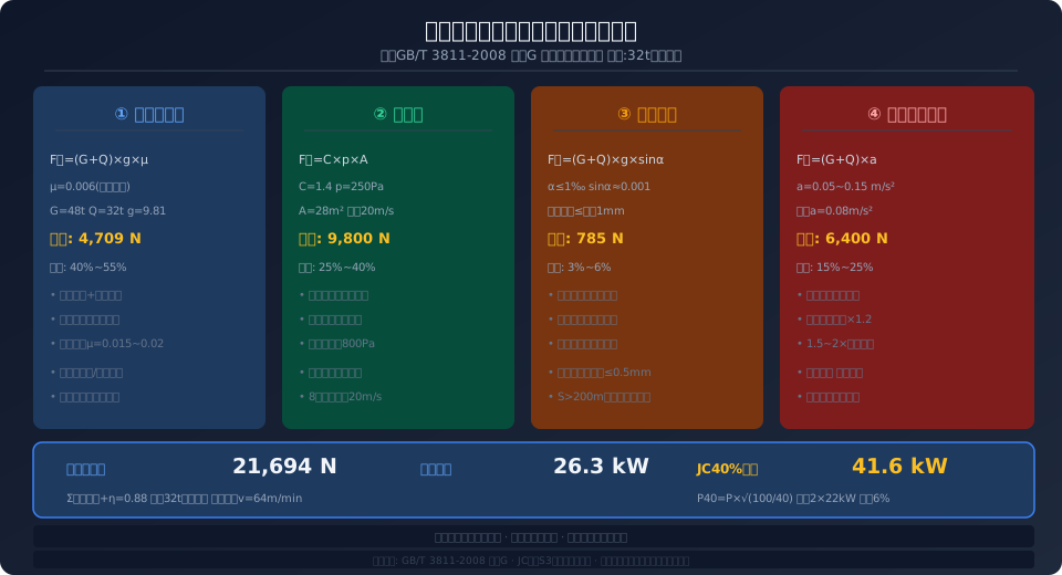
Crane Travel Motor Power Calculation: Static, Wind, Slope & Inertia
Sizing the travel mechanism motor requires sequential verification of four load components: static resistance torque (friction coefficient μ = 0.015–0.02), wind load (gust speed 20 m/s corresponding to a wind pressure of 250 Pa), gradient resistance (rail slope ≤ 1‰), and inertia acceleration torque (acceleration 0.05–0.15 m/s²). The total power must satisfy the S3 equivalent power verification under duty classifications JC40%–JC60%.
Among the four major mechanisms of a crane—hoisting, long travel, cross travel, and slewing—the travel mechanisms do not carry the suspended load directly. However, improper motor sizing can lead to starting difficulties, insufficient grade-climbing capability, or excessive braking distance. Unlike the hoisting motor, which only overcomes gravity, the travel mechanism motor must simultaneously handle four distinct types of resistance torque, making the selection logic more complex and the parameter coupling tighter. This article walks through the complete four-step calculation procedure based on the travel mechanism motor power clauses in ISO 4301 Crane Design Standard, with a worked engineering example.
Crane travel mechanisms are divided into the crane travel mechanism (longitudinal movement of the entire crane along the factory building rails) and the trolley travel mechanism (transverse movement of the trolley along the main girder rails). The calculation logic is identical for both; the differences lie in that the long travel must additionally account for outdoor wind loads and the full dead weight of the crane, while the trolley typically ignores wind loads but must consider the effect of load swing on travel stability. In practice, when multiple bridge drive motors are driven in parallel by a single VFD in a "one-drive-multiple" configuration, the risk of individual motor overload due to uneven load distribution must also be verified.
For modern cranes using integrated "three-in-one" drive units (motor, brake, and reducer in a single assembly), the motor power is jointly determined by the reducer speed ratio and the wheel diameter. The selection process must also simultaneously verify two constraint conditions: the reducer output torque and the wheel load. This article uses a 32 t double-girder bridge crane as an example to demonstrate the complete path from initial parameters to power selection—example parameters: crane dead weight G = 48 t, rated lifting capacity Q = 32 t, long-travel speed v = 64 m/min, wheel diameter D = 630 mm, and crane rail model QU100.
Four-Step Procedure for Travel Motor Power Calculation
The core of travel mechanism motor power calculation is determining the "equivalent power"—that is, the continuous power value corresponding to the actual load the motor experiences during the duty cycle defined by the JC value. According to Annex G of ISO 4301, the equivalent power Pe for the travel mechanism is calculated as: Pe = (Ftotal × v) / (1000 × η), where Ftotal is the total travel resistance (in N), v is the travel speed (in m/s), and η is the transmission efficiency (including reducer and coupling, typically 0.85–0.92). Ftotal is the sum of the following four resistance components:
①Static friction resistance—the sum of rolling friction between the wheels and the rail and bearing friction. Calculation formula: Fstatic = (G + Q) × g × μ, where μ is the combined friction coefficient. When the wheels use plain bearings, μ ≈ 0.015–0.02; with rolling bearings, μ ≈ 0.005–0.008. Using the example parameters (G = 48 t, Q = 32 t, rolling bearings): Fstatic = (48,000 + 32,000) × 9.81 × 0.006 = 4,709 N. This is the base load the motor must continuously overcome, accounting for approximately 40%–55% of the total resistance.
②Wind resistance—a real load that must be included for outdoor crane travel mechanisms but can be neglected for indoor cranes. According to Table 12 of ISO 4301, the maximum calculated wind pressure under working conditions is 250 Pa (corresponding to a wind speed of 20 m/s), and the non-working wind pressure is 800 Pa. Wind resistance Fwind = C × p × A, where C is the wind force coefficient (1.2–1.6 for bridge cranes), p is the calculated wind pressure (250 Pa), and A is the windward area (estimated at approximately 28 m² for the side face of a 32 t double-girder crane). Calculation result: Fwind = 1.4 × 250 × 28 = 9,800 N. Wind resistance is clearly one of the dominant components of total travel resistance. Outdoor trolley travel mechanisms may also need to account for wind load in some cases. Note that wind load is not always "opposing"—when traveling downwind, the wind load becomes negative, but the calculation uses the maximum positive value to cover the most unfavorable condition of starting against the wind.
③Gradient resistance—the additional load caused by rail slope. ISO 4301 requires crane rail slope ≤ 1‰ (i.e., a maximum height difference of 1 mm per meter). Gradient resistance Fgrade = (G + Q) × g × sinα, where sinα ≈ α for small angles. Calculated at a 1‰ slope: Fgrade = (48,000 + 32,000) × 9.81 × 0.001 = 785 N. While the gradient resistance value is relatively small, in large-span factory buildings (rail length > 200 m), the cumulative height difference along the rail can cause locally significant resistance increases. Rail elevation and joint height differences must be strictly controlled during installation.
④Inertia acceleration resistance—the inertial force required to accelerate the entire crane from standstill to rated speed. Finertia = (G + Q) × a, where a is the starting acceleration. ISO 4301 recommends a starting acceleration of 0.05–0.15 m/s² for crane travel mechanisms—lower values for low-speed travel and higher values for high-speed travel. Using a = 0.08 m/s² in this example: Finertia = (48,000 + 32,000) × 0.08 = 6,400 N. It should be noted that the inertial force of the travel mechanism includes both the translational mass and the rotational inertia of rotating parts. For simplified engineering calculations, a factor of 1.1–1.3 is typically applied to account for the additional inertia of rotating components.
Equivalent Power and Duty Cycle Conversion
Once the total resistance is determined, the power at the motor shaft is calculated as: P = Ftotal × v / (1000 × η) = 21,694 × 1.067 / (1000 × 0.88) = 26.3 kW. This value represents continuous power, but crane travel mechanisms do not operate continuously—a single duty cycle includes forward travel, stopping, reverse travel, and load lifting/lowering phases. Therefore, duty cycle (JC) conversion is required based on the actual duty classification.
Crane travel mechanisms typically operate under duty type S3 (intermittent periodic duty), with common duty cycle values of 25%, 40%, or 60%. According to Table G.1 of the ISO 4301 Crane Design Standard, when the reference duty cycle is 40%, the power at other duty cycle values is converted to the 40% reference using: P40 = PJC × √(JC/40). For example, a 30 kW motor initially selected at JC=60% converts to an equivalent power of P40 = 30 × √(60/40) = 36.7 kW at the 40% reference—this appears higher because the motor operates 60% of the time, requiring higher output during the shorter "virtual" 40% duty window to achieve equivalent thermal performance. When selecting equipment, altitude must also be considered (derating required above 1,000 m, with a 1% reduction per 100 m increase) along with ambient temperature (derating required above 40°C, with approximately a 3% reduction per 5°C rise).
Returning to our example: P = 26.3 kW (continuous power), converted to the JC40% reference gives P40 = 26.3 × √(100/40) = 41.6 kW. For actual selection, two 22 kW motors (dual-motor bridge travel drive) can be used, providing 44 kW total power with a 6% margin to meet starting acceleration and short-term overload requirements. After selection, verify that the motor's maximum starting torque exceeds 1.5 to 2 times the total resistance torque (considering the most unfavorable combination of static friction and inertia), and ensure the braking torque of the brake is no less than 1.25 times the maximum wind load plus slope load combination under full-load conditions.
Travel Mechanism Power Quick Reference by Capacity
Travel Mechanism Motor Selection: Key Considerations, Common Pitfalls & IP Ratings
When sizing the travel mechanism motor, engineering considerations go beyond simple power matching. First, starting torque ratio — a standard squirrel-cage asynchronous motor delivers approximately 2.0 to 2.5 times its rated torque at startup. If starting torque proves insufficient, upgrade to a high-breakaway-torque motor or adopt a variable-frequency soft-start scheme to reduce inrush current impact. Second, insulation class — for high-temperature environments such as steel foundries and casting shops, select Class F insulation (allowable temperature rise 105 K) or Class H insulation (125 K), with a protection rating of at least IP54.
For travel mechanisms where multiple motors drive the same crane bridge girder — common on long-span double-girder bridge cranes — an often-overlooked issue is uneven load distribution between motors. Ideally, the VFD uses "master-follower" or "parallel speed control" to command two (or more) motors to output identical torque. In practice, however, minor differences in wheel diameter (manufacturing tolerance ±0.5 mm), rail elevation variations, and slight discrepancies in gearbox efficiency can cause the actual power draw of each motor to differ by 10% to 15%. To prevent any single motor from operating in a sustained overload condition, add a 5% to 8% load-imbalance margin to each motor's calculated power rating, or opt for an inverter drive with independent current feedback (one dedicated VFD per motor) to achieve real-time torque-bias compensation.
Third, choosing between variable-frequency and fixed-speed motors — when the travel mechanism requires variable-frequency speed control (e.g., precise positioning, anti-sway control, multi-crane coordination), use inverter-duty motors (such as the YZP/YGPE series), whose insulation system is designed to withstand the high-frequency harmonic voltage spikes produced by VFD output. Fourth, brake-to-motor power matching — braking torque should be 1.25 to 1.5 times the full-load static torque, and the brake should be mounted coaxially with the motor for ease of maintenance. For outdoor travel mechanisms, include a manual release device so the crane can be towed during a power outage. Additionally, consider the junction box protection rating — IP44 suffices for indoor overhead cranes, while outdoor or high-dust environments (such as cement plants) require IP55 and above. In steel smelting shops where ambient temperatures can reach 65 °C, even Class F insulated motors must be derated by 5% for every 10 °C rise above the rated temperature; otherwise, insulation life degrades rapidly.
Frequently Asked Questions
Q: What motor power is recommended for the long-travel mechanism of a 32-ton double-girder bridge crane?
A: For a 32 t double-girder overhead crane (dead weight 48 t, travel speed 64 m/min), the four-step calculation method yields a total running resistance of approximately 21.7 kN and a continuous power requirement of 26.3 kW. After converting to an equivalent power rating at JC 40%, the figure becomes 41.6 kW. The engineering recommendation is two 22 kW variable-frequency motors. Final selection should factor in shop floor length, rail gradient, outdoor wind load, altitude, and other environmental conditions — a 5% to 10% power margin is advisable.
Q: How does motor power calculation for the travel mechanism differ from the hoisting mechanism?
A: There are three key differences. First, the travel mechanism must overcome four types of resistance — static friction, wind load, gradient, and inertia — rather than a single gravity load. Second, the duty cycle (JC) for travel mechanisms typically ranges from 40% to 60%, whereas hoisting mechanisms use 25% to 40%, resulting in different equivalent power conversion factors. Third, the travel mechanism requires additional verification of starting acceleration and braking distance — undersizing the motor leads to sluggish starts and poor ramp-climbing ability, while oversizing causes aggressive acceleration and wheel slip.
Q: What wind speed should be used to calculate wind load on an outdoor crane travel mechanism, and how is the windward area determined?
A: Per ISO 4301 (formerly ISO 4301, Table 12), the design wind pressure for working conditions is 250 Pa (corresponding to a wind speed of 20 m/s, approximately Beaufort force 8), while the non-working condition wind pressure is 800 Pa (36 m/s, approximately Beaufort force 12). The windward area is calculated from the crane's three-dimensional outer envelope projected in the direction of travel — for a simplified estimate, take the main girder side height × crane span plus the operator cab's projected area. Note: if the crane has wind shields or operates in an open-sided building, increase the windward area by a 10% to 20% safety margin.
Q: How do I choose between a variable-frequency motor and a fixed-speed motor for the travel mechanism? Is the added cost of a VFD solution worth it?
A: Choose a variable-frequency motor (YZP series) when the travel mechanism requires precise positioning, anti-sway control, or coordinated multi-crane speed regulation. Although a VFD solution adds 20% to 30% to the initial investment, it delivers clear returns in the following scenarios: ① workshops with frequent start-stop cycles — VFD reduces start-stop impact by more than 50%, extending wheel and gearbox life; ② long-distance high-speed travel — VFD optimizes the acceleration/deceleration speed curve, reducing peak power demand by up to 30%; ③ multi-crane coordinated scheduling — VFD precisely controls each crane's speed curve to prevent collisions. For simple material handling with low start-stop frequency, a fixed-speed motor with contactor control offers better cost-effectiveness.
Kelude specializes in the design and manufacture of European-standard heavy-duty cranes, offering a product range that includes 50 t to 300 t European-standard double-girder cranes, bridge cranes, and gantry cranes. All products strictly comply with ISO 4301 (Crane Design Standard) and the FEM/DIN international standard system. We provide full life-cycle technical services, from solution design and product selection through to installation and commissioning.
For a travel mechanism selection calculation sheet or a detailed technical solution, contact the Kelude engineering team: 13903802779.