

Gantry Crane Main Girder Welding Process & Quality Control
The Complete Guide to Crane Main Girder Welding Procedures and Weld Quality Control (Including GB/T 5117). Main girder welding is the most critical manufacturing step for box girders and I-beams in overhead and gantry cranes. Weld quality directly determines the girder's load capacity, fatigue life, and operational safety.
Main girder welding is the most critical step in fabricating box girders and I-beams for overhead and gantry cranes. Weld quality directly governs the girder's load-bearing capacity, fatigue life, and in-service safety. This article provides a comprehensive walkthrough of the full welding workflow—from filler metal selection, joint preparation, and welding parameter development to distortion control and weld inspection—referencing GB/T 5117 for covered electrodes for non-alloy and fine-grain steels, GB/T 8110-2017 for carbon and low-alloy steel wires for gas-shielded arc welding, and GB/T 11345 for ultrasonic testing of welds. It serves as a practical reference for welding engineers and quality inspectors alike.
Main Girder Weld Joint Design and Weld Types
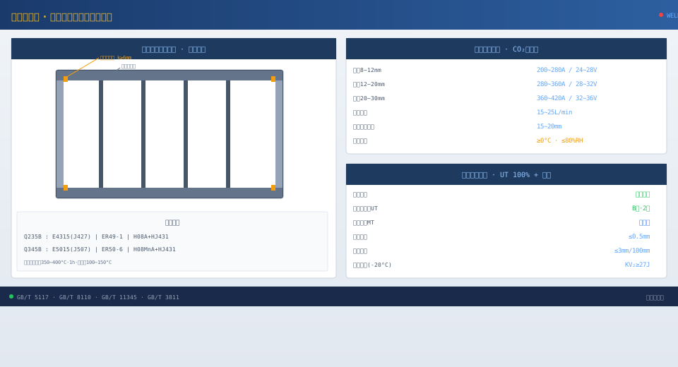
Weld seams in a box girder main girder fall into several categories: the four full-length longitudinal fillet welds joining the flange plates to the web plates—these are the critical welds that carry bending stress—plus fillet welds between the web plates and transverse stiffeners, fillet welds attaching longitudinal stiffeners to the web, and butt welds and fillet welds at the connection between the main girder and the end carriages. Fillet weld sizes are determined per the structural welding provisions of GB/T 3811 Crane Design Standard, typically ranging from 0.7 to 1.0 times the web plate thickness, with a minimum of 6 mm. The longitudinal fillet welds are continuous, and the leg size k is governed by the thinner of the flange plate or web plate: for thicknesses ≤ 20 mm, k ≥ 6 mm; for 20–40 mm, k ≥ 8 mm; and for thicknesses > 40 mm, k ≥ 10 mm. Fillet welds for transverse stiffeners may be intermittent to reduce welding distortion, except within the end quarter-span zones of the main girder, where continuous welding is mandatory. I-beam girders involve two longitudinal fillet welds between the flange plates and the web, plus end plate connection welds—a simpler layout than a box girder, but held to the same stringent quality requirements.
| Comparison Item | CO₂Gas-Shielded Welding | Submerged Arc Welding (SAW) | Shielded Metal Arc Welding (SMAW) |
|---|---|---|---|
| Welding Efficiency | Medium(25~35cm/min) | High(30~40cm/min) | Low(10~20cm/min) |
| Weld Seam Quality | Good | Excellent | Fair |
| Applicable Plate Thickness | 8~30mm | 10~24mm | Optional Thickness |
| Groove Preparation Requirement | No Groove Required | Groove Required | Groove Required |
| Welding Distortion | Moderate | Small | Large |
| Equipment Investment | Medium | High | Low |
| Applicable Weld Seam | Longitudinal Fillet weld(Main) | Full Length Fillet weld | Stiffener / Stiffening Rib/Repair Welding |
Welding Consumable Selection
E4315 (J427)
ER49-1 / ER50-6
H08A + HJ431
E5015 (J507)
ER50-6
H08MnA + HJ431
Joint Preparation and Fit-Up
Longitudinal fillet welds on the main girder are normally welded directly as T-joint fillet welds without beveling. When the web plate thickness exceeds 20 mm, a single-bevel V-groove (bevel angle 45° ± 5°, root face 2 mm) may be machined on the web edge to ensure full penetration. Butt welds used to splice web plates (when additional length is required) are prepared as double-bevel V-grooves or X-grooves with a groove angle of 60° ± 5°, root face 1–2 mm, and a root gap of 2–3 mm. Before assembly, clean the groove faces and the adjacent 20 mm on both sides to remove oil, rust, moisture, and other contaminants, exposing bare metal. Use assembly jigs and fixtures to maintain flange-to-web perpendicularity (deviation no greater than 1/500 of the web height), flange plate parallelism, and overall main girder straightness. Tack welds should be 30–50 mm long, spaced 300–500 mm apart, using the same consumables and parameters as the final weld. Tack welds are to be retained as part of the finished weld.
Welding Parameters for Main Girder Fabrication
Gas-shielded welding with CO₂ is the most common process for longitudinal fillet welds on the main girder. CO₂ purity must be at least 99.5%, with a gas flow rate of 15–25 L/min. Matching current and voltage parameters: for plate thickness 8–12 mm, use 200–280 A, 24–28 V, at a travel speed of 25–35 cm/min; for 12–20 mm, use 280–360 A, 28–32 V, at 20–30 cm/min; for 20–30 mm, use 360–420 A, 32–36 V, at 18–25 cm/min. Maintain electrode stick-out at 15–20 mm. Submerged arc welding is the preferred process for high-volume production of long continuous longitudinal fillet welds on the main girder. Parameters: for plate thickness 10–16 mm, use 500–650 A, 32–36 V, at 30–40 cm/min; for 16–24 mm, use 650–800 A, 34–38 V, at 25–35 cm/min. Shielded metal arc welding is used mainly for stiffener attachment and short end welds; for plate thickness 8–16 mm, use a welding current of 180–240 A with a φ4.0 mm electrode. Welding should not be performed when the ambient temperature is below 0°C or relative humidity exceeds 80%. For CO₂ gas-shielded welding, wind speed must not exceed 2 m/s — use a windbreak when necessary.
Welding Deformation Control
Welding deformation of the main girder is the most common quality issue encountered during fabrication. It typically manifests as side bow (lateral curvature of the girder in the horizontal plane), camber deviation (the upward camber in the vertical plane failing to meet design requirements), and torsional distortion (twisting of the girder about its longitudinal axis). Process controls to minimize welding deformation include: symmetrical welding sequences (alternating between the longitudinal fillet welds on one side and the corresponding welds on the opposite side to avoid continuous single-side welding), backstep welding (dividing long welds into 300–500 mm segments and welding from the center toward both ends, allowing each segment to cool to hand-touch temperature before proceeding), preforming (presetting a counter-deformation during assembly—for example, building in 10–15 mm of extra camber so the girder springs back to the design value after welding), rigid fixturing (securing the girder in a welding jig to restrain movement during welding), and optimized weld sequencing (completing the web plate splice welds first, followed by the fillet welds connecting stiffeners to the web, and finally the full-length longitudinal fillet welds). After welding, the girder undergoes overall straightening, using either flame straightening (heating the flange plate or web in the deformed zone with an oxy-acetylene torch to 600–650°C and allowing natural cooling to induce shrinkage) or mechanical straightening (cold straightening with a press machine). Flame straightening temperatures must not exceed 900°C to avoid degrading the base material properties.
Weld Quality Inspection and Acceptance Standards
Weld quality inspection is performed in accordance with GB/T 11345 and GB/T 29712, and is carried out at three levels: visual inspection, non-destructive testing, and mechanical property testing. Visual inspection is conducted on all welds and covers surface profile uniformity, the presence of cracks, porosity, slag inclusion, lack of fusion, undercut (undercut depth not exceeding 0.5 mm, with cumulative length not exceeding 10% of the total weld length), and whether the leg size meets design requirements. Non-destructive testing employs Ultrasonic Testing (UT) for 100% inspection of longitudinal fillet welds and splice welds, with an inspection grade of no less than B and an acceptance grade of no less than 2. Magnetic Particle Testing (MT) is used to detect surface and near-surface defects on butt welds and on the fillet welds of transverse stiffeners located in tension zones. Ultrasonic testing is performed to GB/T 11345 using probe frequencies of 2.5–5 MHz, with a detection sensitivity of no less than a φ2×40 mm transverse hole. Mechanical property testing is carried out during the procedure qualification stage and includes tensile testing, bending testing, and impact testing of the weld metal (KV₂ ≥ 27 J at −20°C). One procedure test plate is welded for each batch of test plates to verify mechanical properties. Acceptance criteria: no cracks, lack of fusion, or incomplete penetration are permitted anywhere in the weld; individual porosity must not exceed 3 mm in diameter, with no more than 3 pores per 100 mm of weld length; and linear slag inclusions must not exceed 10 mm in length, with a spacing of at least 6 times the inclusion length.
