

Crane Anti-Sway Control: From Input Shaping to Adaptive Control
Crane Anti-Sway Control: Principles and Engineering Implementation — From Input Shaping to Adaptive Control. Crane anti-sway control is a key technology for improving the operating efficiency and positioning accuracy of bridge cranes. By suppressing load swing during acceleration, deceleration, and steady-state travel, it significantly shortens work cycles while enhancing lifting safety.
Crane anti-sway control is essential for maximizing the efficiency and positioning accuracy of overhead cranes. By minimizing load oscillation during acceleration, deceleration, and travel, this technology shortens cycle times and improves overall lifting safety. This article provides a comprehensive overview of anti-sway control principles and the main technical approaches — from open-loop input shaping to closed-loop adaptive control — along with practical parameter tuning methods and on-site commissioning steps based on real-world engineering experience.
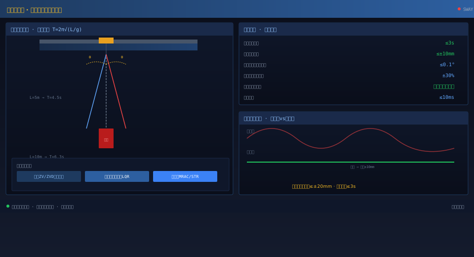
Understanding Load Swing Dynamics in Overhead Cranes
The load suspended from an overhead crane behaves essentially as a physical pendulum — or a double-pendulum system — with a varying rope length. When the trolley or crane bridge accelerates, decelerates, or runs at a constant speed, the load swings away from the vertical due to inertia, creating an oscillation angle. The swing frequency is determined by the rope length and is calculated using the simple pendulum period formula T=2π√(L/g), where L is the rope length in meters and g is the gravitational acceleration (9.81 m/s²). For example, a rope length of 5 m produces a swing period of approximately 4.5 seconds, while 10 m yields about 6.3 seconds. Load swing affects operational efficiency in three key ways: operators must wait for the oscillation to decay before proceeding with the next move (typically 30–60 seconds); swing makes it difficult to align the load with the target position during lowering, requiring repeated inching corrections; and excessive swing poses a collision risk with nearby equipment or personnel. The goal of anti-sway control is to keep residual swing amplitude within ±20 mm when the trolley comes to a stop, while reducing swing decay time to under 3 seconds.
| Comparison Item | Open-Loop Input Shaping(ZV/ZVD) | Closed-Loopstate observer LQR | Adaptive Control(MRAC/STR) |
|---|---|---|---|
| Sensor Requirement | None Required Sensor | Required Inclination Sensor/Vision | Required Encoder+Inclination Sensor |
| Computational Complexity | Low(PLCSufficient) | Medium(Required S7-1500) | High(Required S7-1500) |
| Cable Length Adaptability | Fixing Parameter±30% | Adaptable to Variations | Real-Time Adaptive Optional Cable Length |
| External Disturbance Rejection | None | Strong | Strong |
| Implementation Cost | Low(No Additional Hardware) | Medium(No Additional Hardware Sensor) | Medium-High |
| Application Scenarios | Standard Hoisting Operation | Precision Assembly | Multi-Condition Variable Cable Length |
| Residual Sway | ≤±20mm | ≤±10mm | ≤±10mm |
Open-Loop Anti-Sway Control with Input Shaping
Zero Vibration · Two-Pulse
Zero Vibration & Derivative · Three-Pulse
Real-Time Parameter Updating
Closed-Loop Anti-Sway Control with State Observer
Closed-loop anti-sway control measures the load sway angle in real time using an inclination sensor mounted above the lifting spreader or a vision camera. The measured signal is fed back to the controller, which generates corrective commands to suppress sway caused by external disturbances—on top of the baseline open-loop shaping. A state observer (e.g., Kalman filter or Luenberger observer) estimates the full system state vector from trolley position, trolley speed, and load sway angle, which is then used to compute the state-feedback control law. Typical closed-loop anti-sway controllers are designed using LQR (Linear Quadratic Regulator) or pole-placement methods, with the control law expressed as u = −Kx, where u is the trolley acceleration command, x is the system state vector (including trolley position, trolley speed, sway angle, and angular velocity), and K is the feedback gain matrix. Closed-loop control significantly outperforms open-loop shaping in rejecting external disturbances such as wind loads or initial sway angles caused by off-center loading. However, it requires an inclination sensor or vision camera to provide the sway-angle feedback signal.
Adaptive Control for Variable Rope Lengths
In real crane operations, the hoist rope length changes continuously during lifting, making the system model time-varying. Adaptive anti-sway control addresses this by estimating system parameters online and adjusting controller parameters in real time to compensate for rope-length variations. Two main implementation approaches exist: Model Reference Adaptive Control (MRAC) and Self-Tuning Regulation (STR). MRAC defines an ideal reference model (e.g., a sway-free trolley system), compares the actual system output against the reference model output, and adjusts controller parameters online to drive the actual system toward the reference behavior. STR performs system parameter identification (using Recursive Least Squares, RLS) and control-law computation in each control cycle, making it well suited for crane operations with rapid rope-length changes. Adaptive control demands higher computational power—typically requiring a high-performance PLC (such as the S7-1500) or a dedicated motion controller, with a control cycle time of no less than 10 ms. In practical engineering applications, adaptive input shaping (adaptive ZV or ZVD) is often preferred: the shaper delay parameters are looked up or computed in real time based on the current hoist height.
System Configuration and Sensor Selection
Sensor configurations for anti-sway systems vary depending on the control scheme. The open-loop input-shaping approach requires no additional sensors—the existing hoist height encoder signal is read directly from the PLC or VFD, and the sway period is calculated from the rope-length formula to update the shaper delay parameters in real time. The closed-loop feedback approach requires additional sway-angle sensing: an inclination sensor mounted at the wire-rope fixing point above the lifting spreader (measuring range ±30°, accuracy better than 0.1°, output 4–20 mA or SSI signal transmitted via trailing cable or wireless link to the PLC), or a vision camera mounted on the trolley platform looking down at the spreader and load, with image-processing algorithms extracting the sway angle to an accuracy of ±0.05°. Sensor data is interfaced to the PLC via PROFINET or analog input modules. The actuation system uses the existing crane bridge and trolley VFDs—no additional drives are required. Recommended minimum hardware configuration: S7-1200 or S7-1500 PLC, VFDs with speed-setpoint ramp inputs (e.g., G120), and a multi-turn absolute encoder for hoist height measurement.
Parameter Tuning and Commissioning
Anti-sway control parameter tuning is performed in three steps. Step 1 — System parameter calibration: Raise the hoisting mechanism to an intermediate height (e.g., 5 m), run the trolley at constant speed, and record the load sway period (observable as a periodic component in the laser distance sensor or encoder signal). Use the sway-period formula to back-calculate the equivalent rope length. Step 2 — Open-loop parameter tuning: Set the input shaper delay times and pulse amplitude ratios in the trolley PLC program or VFD. Start with short travel distances (3–5 m) and gradually increase to full span, observing sway amplitude and decay time. Adjust parameters to minimize residual sway. Step 3 — Feedback parameter tuning (closed-loop systems only): After open-loop tuning is complete, enable the closed-loop feedback control. Start with a small proportional gain and gradually increase the gain coefficients while monitoring dynamic response and stability. Use step-response tests to evaluate response speed and overshoot. During commissioning, use the PLC's oscilloscope function or the VFD's trace-recording capability to capture trolley speed commands and load sway-angle waveforms, using the waveform analysis to guide parameter adjustments. Acceptance standard: After the trolley comes to a stop, residual load sway must not exceed ±10 mm (under rated load and standard rope length), and sway decay time must not exceed 3 seconds.
