Non-Standard Crane Design: 5 Core Technologies

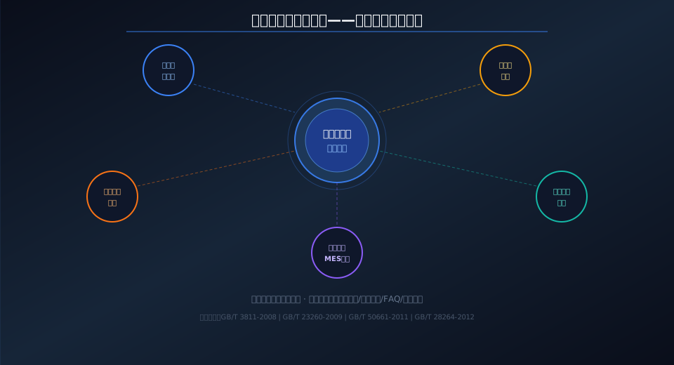
Non-standard crane design spans five core engineering disciplines: end carriage and wheel block design calculations, dual-hoist point synchronization, welding deformation control for long spans, travel mechanisms for curved rails/steep gradients/heavy loads, and control cabinet integration with MES automation interfaces. This collection brings together five in-depth technical articles covering the toughest challenges in non-standard crane engineering and their field-proven solutions. Kelude Heavy Industry has built extensive hands-on expertise through non-standard projects, grounded in the ISO 4301 Crane Design Standard (ISO 4301).

Non-standard cranes must break free from standard product limitations to meet demanding working environments, load conditions, and process requirements. Every stage of the design and manufacturing process presents unique technical hurdles and engineering solutions—from wheel load distribution across end carriages and wheel blocks, to synchronization accuracy in dual-hoist point lifting; from suppressing welding distortion in long-span main girders, to designing travel mechanisms for curved rails and steep gradients, and finally to control cabinet integration with MES automation. With over a decade of engineering experience in non-standard crane design, Kelude Heavy Industry has organized this series around five core technical pillars to lay out a systematic approach to the discipline.

Non-standard crane design: five core technical disciplines overview

Core Technical Articles at a Glance

← Scroll left / right to view full table →
No. Technical Field Core Content Link
01 End Carriageand Wheel Block Box-type Welding End Carriage Design, driving wheel+Idler Wheel Configuration, Wheel load Unevenness Coefficient K=1.1~1.3, Crane Rail Adaptation Engineering Read
02 Double Lifting Points Synchronous hoisting electrical shaft(Servo Ether CAT)Accuracy Less Than0.1Degrees, mechanical shaft(Drive Shaft+Coupling)Accuracy Less Than1Degrees, Scheme Selection Comparison Read
03 Welding Deformation Control Reverse Deformation Amount of Camber20~40mm, Welding Sequence: Center First, Then Edges, Preheating Post-Heating Process, Vibratory Stress Relief Read
04 Curved Rail Steep Slopeheavy-duty wheel Curved Rail R=3~10mand Steep Slope5%~15%Design Key Points, heavy-duty wheel Diameter200~800mm Tread surface Hardness HRC45~55 Read
05 Control Cabinetand MESInterface PLC+Frequency Inverter / VFD+Servo+OPC UA/MQTTArchitecture, Heat Dissipation EMCWiring, Safety Circuit, Fault Diagnosis System Read

End Carriageand Wheel Block

Box-type Welding End Carriage+Drive and Idler Wheel Configuration+Wheel load Unevenness Coefficient K=1.1~1.3+Crane Rail Adaptive Design.Unit-by-Unit Calculation for Non-Standard Conditions End Carriage Cross-Section and Wheel load Distribution.

Read Full Article →

Double Lifting Points Synchronous hoisting

electrical shaft(Servo Ether CATAccuracy Less Than0.1Degrees)vs mechanical shaft(Drive Shaft+Coupling Accuracy Less Than1Degrees).Long Distance Greater Than15mSelectionelectrical shaft, Medium/Short Distance Selectionmechanical shaft.

Read Full Article →

Welding Deformation Control

Reverse Deformation Amount of Camber20~40mm+Welding Sequence: Center First, Then Edges+Preheating Post-Heating+Vibratory Stress Relief.Residual Stress Reduction40%~60%, Primary Welding Pass Rate Greater Than or Equal To95%.

Read Full Article →

Curved Rail Steep Slope Heavy-Duty

Curved Rail R=3~10mTrack Gauge / Rail Gauge Widening5~15mm+Steep Slope5%~15%Power Increase20%~40%+heavy-duty wheel Diameter200~800mm HRC45~55.

Read Full Article →

Control Cabinetand MES

PLC+Frequency Inverter / VFD+Servo+OPC UA/MQTTButt Joint.Heat Dissipation EMCWiring+Safety Circuit SIL2+Fault Diagnosis+MESData Acquisition and Command Dispatch.

Read Full Article →

Related Topics

Non-Standard Crane Customization Complete Guide, crane main girder Design and Finite Element Analysis, crane Electrical Control System Full Design Process, overhead crane Safety Monitoring and Management System.

View Topic →

End Carriage & Wheel Block Design Calculations

The end carriage and wheel blocks are core components of the crane's travel mechanism. The end carriage features a box-section welded structure made of Q355B (≈S355JR), with a section height of L/12 to L/15 of the span. Wheel block configurations include diagonal drive (2 driving wheels + 2 idler wheels) and full drive, with driving wheels mounted in angular bearing housings at diagonal positions. The wheel load unevenness coefficient K ranges from 1.1 to 1.3, and rail contact stress verification follows GB/T 23260-2009. For non-standard designs, the end carriage length and wheel base must be calculated individually for each crane — standard drawings cannot be reused. Read more: End Carriages & Wheel Blocks — Wheel Load Distribution and Rail Adaptation in Non-Standard Crane Design

Dual-Point Synchronous Hoisting: Electrical vs. Mechanical Shaft

Dual-point synchronous hoisting can be achieved through either an electrical shaft or mechanical shaft configuration. The electrical shaft approach uses servo motors + encoders + EtherCAT/PROFINET bus communication to maintain angular deviation below 0.1 degrees with no distance limitations, but the servo system adds 30%–50% to the cost. The mechanical shaft uses a drive shaft + coupling for forced synchronization, achieving accuracy within 1 degree at 20%–40% lower cost — however, the synchronous shaft length should not exceed 15 m. For workpieces longer than 15 m or with more than 3 lifting points, the electrical shaft is the preferred choice. Read more: From Dual-Point Synchronization to Hoisting Systems — Electrical vs. Mechanical Shaft Comparison for Non-Standard Cranes

Welding Deformation Control for Long-Span Box Girders

Welding deformation control for long-span box girders combines multiple techniques: the reverse-deformation method (camber of 20–40 mm), symmetrical welding sequence, segmented back-step welding (300–500 mm per segment), and vibratory stress relief. Longitudinal shrinkage ranges from 0.3 to 1 mm/m, while transverse shrinkage ranges from 0.5 to 2 mm/m. Plates thicker than 25 mm require preheating to 50–200°C. After vibratory stress relief, residual stress is reduced by 40%–60%, and the first-pass welding acceptance rate reaches 95% or higher. Read more: Controlling Welding Deformation in Long-Span Non-Standard Cranes — Reverse Welding Sequence & Stress Relief Techniques

Curved Rail, Steep Grade & Heavy-Duty Travel Mechanisms

Key parameters for curved rail design: minimum radius R = 3–10 m, rail gauge widened by 5–15 mm, guide rollers for assisted turning, and travel speed less than 20 m/min on curved sectionsed sections. For steep grades: slope of 5%–15%, drive power increased by 20%–40%, brake capacity increased by 30%–50%, with anti-slip devices working in conjunction with both electrical and mechanical braking. Heavy-duty wheels: diameter 200–800 mm, tread surface hardness HRC 45–55, hardened layer depth ≥ 15 mm, and bearing service life ≥ 10,000 hours. Read more: Curved Rails, Steep Grades & Heavy-Duty Wheels — Three Critical Challenges in Non-Standard Travel Mechanism Design

Control Cabinet Integration & MES Automation Interface

The control cabinet is built around a PLC core, connecting frequency inverters and servo drives via PROFINET/EtherCAT bus. The standard architecture includes: PLC + frequency inverters (hoisting / long travel / trolley) + HMI touchscreen + industrial gateway. Thermal design keeps the cabinet temperature rise below 30 K, and EMC compliance is ensured through segregated cable routing for power, control, and communication lines. Upward integration via OPC UA/MQTT connects to MES systems, collecting status, fault, and energy consumption data while receiving lifting tasks and positioning commands. Read more: Non-Standard Crane Control Cabinets — PLC Programming, Automation Interfaces & MES Integration Workflow

Further Reading

Non-standard crane design spans a wide range of disciplines. Beyond the five core technologies covered in this article, the following resources offer additional reference: The Complete Guide to Non-Standard Crane Customization walks through the entire process from requirements analysis to acceptance and handover; Crane Main Girder Structural Design & Finite Element Analysis provides a full methodology from load calculations to deflection verification; Overhead Crane Electrical Control System Design — Full Workflow covers engineering practice from schematic drawing to PLC commissioning; and Non-Standard Customization — Technical Deep Dive addresses special design considerations for extreme operating conditions.

Frequently Asked Questions

Q: What is the biggest difference between non-standard crane design and standard crane design?

A: Standard cranes are manufactured from series-produced drawings with fixed parameters, consistent structures, and standardized manufacturing processes. Non-standard cranes require individual design for each unit — from end carriage length, wheel base adjustments, and wheel block configuration to control logic, everything is customized. The design challenges manifest in three areas: ① significantly increased calculation workload (structural calculations and stiffness verification must be redone for every crane); ② greater manufacturing complexity (welding deformation control, non-standard rail adaptation, etc.); ③ extended commissioning timelines (specialized control system programming plus automation interface integration). Design costs for non-standard cranes typically run 1.5 to 2 times that of standard models.

Q: How long does the non-standard crane design phase take?

A: A typical non-standard crane design cycle is 20–40 working days. This breaks down as follows: conceptual design (load calculations + preliminary structural selection + design review) takes 5–10 days; detailed design (steel structure drawings + electrical schematics + PLC programming) takes 10–15 days; and process design (welding procedures + assembly processes + commissioning plan) takes 5–10 days. If finite element analysis is required (for extra-long spans or special structures), add 5–10 days to the schedule. Kelude Heavy Industry grades design timelines by project complexity and can accommodate expedited requests.

Q: Which national standards apply to non-standard crane design?

A: Non-standard crane design primarily follows these Chinese national standards: ISO 4301 Crane Design Standard (overall structural, mechanism, and stability design), GB/T 23260-2009 Crane Wheels (wheel selection and fatigue life calculations), GB/T 50661-2011 Steel Structure Welding Specification (welding procedure qualification records and welder qualifications), GB/T 28264-2012 Safety Monitoring and Management System (safety monitoring system design requirements), and JB/T 10560-2006 Crane Welding Technical Conditions (welding quality and flaw detection standards). Kelude Heavy Industry strictly adheres to the full set of standards listed above.

Q: What is the total timeline from design to delivery for a non-standard crane?

A: From contract signing to equipment delivery and acceptance, the typical cycle is 60–120 days. This includes: design phase 20–40 days, material procurement 5–10 days, manufacturing 20–40 days (welding + assembly + coating), electrical integration 10–15 days, commissioning and inspection 5–10 days, and on-site installation 5–10 days. For projects requiring finite element analysis, special material procurement, or special environmental testing, add 15–30 days to the schedule. Kelude Heavy Industry can adjust delivery timelines based on project urgency.

Related News

contact

contact us

phone:
+86 13903802779

mail:3915269@qq.com

Working hours: Monday to Friday

Wechat
Wechat
SHARE
TOP