

Overhead Crane Positioning: Laser vs Encoder vs UWB
High-precision positioning is the backbone of unmanned crane operations. Positioning accuracy across all three axes directly determines the success rate of automatic grab-and-place cycles and overall efficiency. L3 automation requires X/Y-axis accuracy of ±10mm and Z-axis of ±5mm; L4 unmanned operation demands X/Y-axis accuracy of ±3mm and Z-axis of ±2mm.
A high-precision positioning system is the foundation for unmanned and fully automated crane operations. Positioning accuracy on the crane bridge X-axis (factory longitudinal travel, 30–200m), the trolley Y-axis (factory transverse travel, 10–50m), and the hoisting Z-axis (vertical, 5–20m) directly impacts the success rate of automatic grab-and-place cycles and operational efficiency. L3 automated cranes require positioning accuracy of ±10mm on the X/Y axes and ±5mm on the Z-axis, while L4 unmanned cranes demand ±3mm or better on the X/Y axes and ±2mm on the Z-axis. This article provides a comprehensive technical comparison of the six mainstream positioning sensor technologies used in industrial crane systems today—laser distance sensors, encoders, barcode tape, Gray-code bus positioning, UWB, and vision-based positioning—covering operating principles, accuracy, cost, installation requirements, and application scenarios for each. It also includes complete SCL code for PLC complementary filtering and Kalman filter fusion algorithms, plus a full commissioning checklist and sensor selection decision workflow from component choice through site acceptance testing.
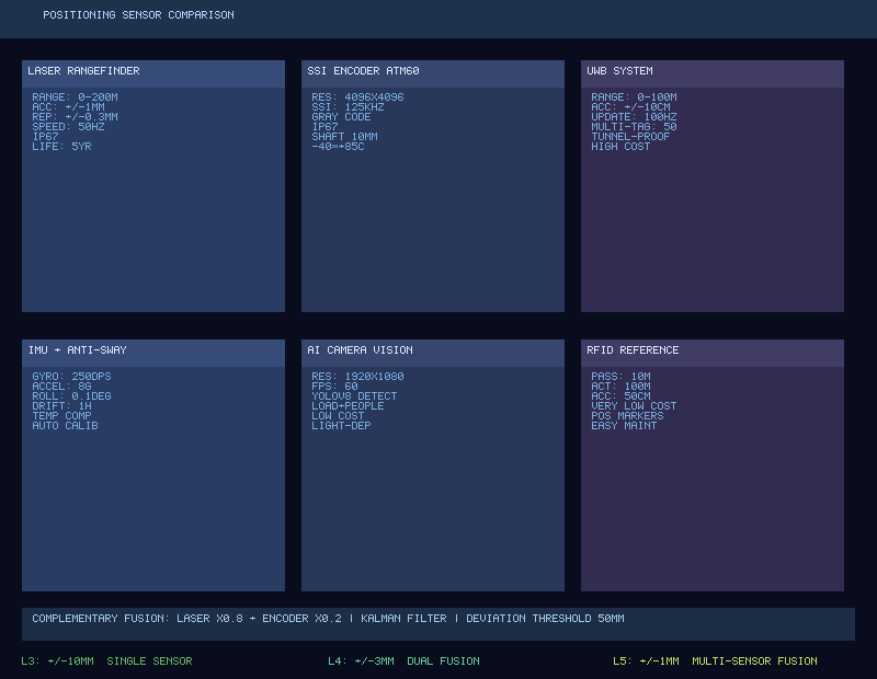
Laser Distance Sensors for Crane Positioning
Laser distance sensors calculate distance by measuring time-of-flight (TOF) or phase difference of the laser beam, making them the highest-accuracy single-sensor solution for crane positioning. Recommended models: SICK DME5000-123 (measuring range 0.1–300m, accuracy ±2mm, SSI/PROFINET dual output, IP65 rated, ¥8000) and Leuze AMS 304i (measuring range 0.2–300m, accuracy ±1.5mm, ¥7500). The domestic brand Kehui KH-LD100 (accuracy ±5mm, RS485/4–20mA, ¥3000) offers excellent value for budget-constrained projects.
Installation requirements: The laser distance sensor mounts on the crane end carriage, with the reflector plate installed on the factory column—the laser path must remain unobstructed at all times, and the crane must stay within the laser's ±30° field of view throughout its travel. The reflector surface requires regular cleaning (recommended monthly; weekly in foundry environments). In heavy dust conditions, a compressed air purge system can be added (approximately ¥500 per set, including solenoid valve, air hose, and nozzle). The SSI interface uses twisted-pair shielded cable up to 100m, with shield single-point grounding at the PLC side. The PROFINET version simplifies wiring; IP address and DeviceName are configured in TIA Portal (e.g., laser-x-axis, IP 192.168.1.51). Pros and cons: This is the preferred solution for maximum accuracy (±1.5–2mm), but signal interruption occurs when the laser path is blocked (e.g., when other cranes cross the bay), reflector contamination causes distance reading jumps, and heavy steam in smelting workshops during summer can render the system completely inoperative.
Encoder-Based Positioning for Overhead Cranes
Absolute multi-turn encoders are the standard positioning sensor for overhead cranes. Recommended models: Sick ATM60-P4H12x13 (4096 pulses/rev × 4096 revolutions, SSI/PROFINET, ¥3000) and Heidenhain ECN 1313 (23-bit resolution, i.e., 8,388,608 pulses/rev, EnDat 2.2 interface, ¥4500). Absolute encoders retain their position after power loss without requiring re-homing on startup, making them the preferred encoder type for industrial crane positioning. Incremental encoders (e.g., Omron E6B2-CWZ6C, 2000 P/R, push-pull output, ¥400) are inexpensive but lose position on power failure; they are not recommended as the primary positioning sensor and should only be used as a backup or for speed feedback.
Three mounting configurations compared: Option A—motor tail shaft mounting: The encoder connects to the motor tail shaft via a coupling. Installation is straightforward (shaft alignment within ±0.1mm coaxiality required), and travel distance is calculated from motor rotation angle. However, wheel slip cannot be compensated (deviation can reach 10–30mm when wheels are worn or rails are contaminated with oil). Option B—wheel axle mounting: The encoder connects to the crane wheel axle via a coupling, directly measuring travel distance. This provides better accuracy than Option A and can detect slip, but wheel diameter wear requires periodic calibration compensation (quarterly laser comparison to correct the scale factor). Option C—rack-and-pinion mounting: A rack is installed alongside the crane rail, and the encoder's pinion gear meshes with the rack to measure travel. This offers the highest accuracy with zero slip, but rack installation is costly (¥200–300/m including installation) and maintenance-intensive (periodic lubrication and cleaning required). Recommended engineering approach: Use Option A (motor tail shaft) on both X and Y axes, fused with a laser distance sensor via complementary filtering—the laser's long-term accuracy calibrates the encoder's short-term continuity.
Resolution calculation: The conversion coefficient from encoder pulses to actual distance is K = π × D / (N × 4), where D is the wheel diameter in mm, N is the encoder resolution in pulses per revolution, and 4 is the quadrature multiplier. Example: with D = 500mm and N = 4096, K = 0.0958mm/pulse. Accuracy calibration method: Run the crane over a 10m distance, compare the encoder measurement against the laser measurement (or manual tape measure), and correct using Knew = theoretical distance × Kold / measured distance. TIA Portal TM PosInput 2 module configuration: operating mode SSI absolute encoder, encoder type SSI 25-bit (13-bit × 4096 revolutions), baud rate 125kHz, data length 25 bits, Gray code with automatic PLC conversion to binary, monostable trigger time 20μs, monitoring time 100ms with timeout alarm.
Barcode Tape Positioning Systems for Cranes
Barcode tape positioning involves laying a barcode tape along the crane rail, with a barcode reader mounted on the crane scanning to obtain absolute position. Typical models: Sick LMS series readers (¥5000–7000 each), barcode tape (¥50–80/m including installation)—for a 100m rail, this totals approximately ¥5000–8000. Accuracy is ±0.2mm/m, meaning a 100m rail accumulates ±20mm error. The gap between reader and tape should be 20–100mm. The tape must be installed parallel to the rail within ≤5mm, and the surface must not be covered with paint or oil—in practice, tape wear is the primary failure mode, with a service life of approximately 3–5 years requiring full replacement. The advantages of barcode tape are absolute position measurement, no accumulated error, and simpler installation than Gray-code bus systems. Limitations: surface contamination increases read failure rates (positioning becomes unreliable when the miss rate exceeds 5%), replacement is costly (the entire rail length must be replaced), and the system is unsuitable for foundry environments with dust and oil contamination.
Gray-Code Bus Positioning for Long-Travel Cranes
The Gray-code bus positioning system (magnetostrictive encoder) measures the reader head's absolute position along the bus rail using electromagnetic induction, achieving ±0.1mm accuracy with a measuring range up to 1000m. It is the preferred solution for ultra-long-travel cranes, such as container cranes at port terminals (500–1000m) and stacker reclaimers in stockyards (200–500m). The Gray-code bus system carries a higher cost—bus rail at ¥200–300/m, reader head at ¥8000–12000 each, bringing a 100m rail to approximately ¥30000–50000 total including installation. The system is completely contactless and wear-free, with a service life exceeding 10 years, and is impervious to dust, water mist, and oil—this is its greatest advantage over laser and barcode tape solutions in harsh metallurgical and port environments. Installation accuracy requirements are demanding—bus rail straightness deviation must be ≤±2mm per 10m, and each sleeper requires height fine-tuning after installation (approximately 0.5 person-days per 100m). When applied on overhead cranes, the gap between the reader head and the bus rail must be maintained at 3–5mm (deviation beyond ±1mm degrades signal strength), and no metal objects may intrude within ±50mm of the bus rail during crane travel, as this causes electromagnetic interference.
UWB and Vision-Based Positioning for Cranes
UWB (Ultra-Wideband) Positioning: Deploy 4–8 UWB positioning base stations across the facility (¥2000–5000 each), with UWB tags mounted on the crane (¥500–1000 each). Three-dimensional coordinates are calculated using time-difference-of-arrival (TDOA) algorithms. Accuracy is ±10–30cm (depending on base station density and environmental multipath effects), with a total system cost of approximately ¥20000–50000 per workshop. The advantages of UWB are broad coverage (a single base station covers a 30–50m radius) and no need for cabling along the crane rail—making it ideal for retrofit projects in existing factory buildings by minimizing civil construction work. However, UWB positioning accuracy is far lower than laser or encoder solutions (cm-level vs. mm-level), limiting its use to personnel position monitoring and crane anti-collision warning applications where high precision is not required. It cannot serve as a precision positioning sensor for automatic grab-and-place operations.
Vision-Based Positioning: Uses industrial cameras to capture QR codes or fiducial markers on the floor or walls, then calculates the crane position via perspective transformation. Accuracy: ±5–15 mm (depending on camera resolution, installation height, and marker density); cost: approximately ¥5,000–15,000 per system. The Hikrobot CRA-200 (stereo vision + edge AI, ¥3,800 per unit) supports calibration-free installation, lowering the deployment barrier. Advantages of vision-based positioning: simple installation (camera mounts on the underside or side of the crane bridge, pointing down at floor markers), immune to wheel slip, and can double as a safety monitoring tool (detecting personnel entering the rail area). Limitations: sensitive to lighting changes (dark workshops require supplementary lighting, e.g., LED high-bay lights ≥30 W), markers need periodic maintenance (dirty or worn QR codes degrade recognition), and processing latency of 20–40 ms is higher than laser's <5 ms. For standard factory buildings with good existing lighting, vision-based positioning can serve as the primary positioning solution for L3-level cranes, offering better cost-effectiveness than a laser + encoder combination.
6. Sensor Data Fusion Algorithms (PLC SCL Code)
Every single-sensor approach has inherent limitations—lasers are vulnerable to obstruction and contamination, encoders suffer from slip and accumulated error, barcode tapes wear out and are costly to replace, and UWB lacks precision. In industrial practice, multi-sensor fusion is recommended, with laser + encoder complementary filtering being the most mature and reliable technical route for crane positioning. Core logic of complementary filtering: the encoder provides short-term dead reckoning via #estimated_pos := #fused_pos + #encoder_delta (where #encoder_delta is the encoder position difference between the current and previous frame). When the laser is valid, fusion is applied: #fused_pos := α×#laser_pos + (1−α)×#estimated_pos, with α typically set to 0.8 (the laser's high weight ensures no long-term drift, while the encoder's 0.2 weight provides smooth inter-frame continuity). Deviation monitoring: when #fusion_error exceeds 50 mm, a confidence check is triggered—if the laser is stable (#laser_pos change <20 mm/frame) but the encoder jumps, the encoder is deemed to be slipping and #estimated_pos is reset to #laser_pos; if the laser jumps (#laser_pos change >50 mm/frame) while the encoder is stable, the laser reading is deemed anomalous (e.g., spurious reflection or reflector switching), so the system trusts the encoder (#fused_pos := #estimated_pos) and raises an alarm. If the laser becomes completely unavailable, the system relies purely on encoder dead reckoning (#fused_pos := #estimated_pos) and issues a degraded-mode alarm to the operator.
For higher-precision fusion, a Kalman filter is used (suitable for L4-level ±2 mm applications). The Kalman filter uses crane position p and velocity v as the state vector, with laser distance measurement z as the observation. Prediction step—#x_pred[0] := #x_est[0] + #x_est[1]×#dt, covariance prediction #P_pred := #P + #Q. Update step (when laser is valid)—Kalman gain #K := #P_pred / (#P_pred + #R), position update #x_est[0] := #x_pred[0] + #K×(#laser_pos − #x_pred[0]), velocity update #x_est[1] := #x_pred[1] + #K×(#laser_vel − #x_pred[1]), covariance update #P := (1−#K)×#P_pred. Tuning parameters: #Q (process noise covariance) reflects encoder noise level (default 0.1), #R (observation noise covariance) reflects laser noise level (default 0.01), #P initial covariance defaults to 1.0, and #dt sampling period is 0.005 s. Compared to complementary filtering, the Kalman filter's advantage is that it estimates both position and velocity simultaneously with a more explicit noise model; its disadvantage is more complex tuning (requires understanding the physical meaning of covariance matrices).
Recommended L4-level high-precision solution: triple-redundant fusion of laser + encoder + barcode tape—laser weight 0.7 for primary positioning, encoder weight 0.2 for short-term continuity, and barcode tape weight 0.1 providing absolute position calibration every 100 ms. If any single sensor fails, the system automatically degrades to dual-sensor fusion while still meeting L3 accuracy (±10 mm). If any two sensors fail, it degrades to single-sensor operation and triggers a stop alarm. Soft speed limiting filters out jumps—the laser position change rate is capped at the maximum physical speed (#max_delta := #MAX_SPEED×0.005, #laser_filtered := LIMIT(#fused_pos−#max_delta, #laser_pos, #fused_pos+#max_delta)).
7. Selection Decision Process & Cost Comparison
Comparison of Six Positioning Technologies: Laser distance sensor—accuracy ±1.5–5 mm, cost approximately ¥3,000–8,000 per axis, highest maturity level, limitation: susceptible to obstruction and contamination. Absolute multi-turn encoder—accuracy depends on mounting method (motor tail shaft ±5–10 mm, wheel ±3–5 mm, rack-and-pinion ±1–2 mm), cost approximately ¥3,000–5,000 per axis, high maturity, limitation: slip and wheel wear. Barcode tape—accuracy ±0.2 mm/m, cost approximately ¥5,000–8,000 per 100 m plus reader head ¥5,000–7,000, limitation: wear and replacement. Gray-code bus positioning system—accuracy ±0.1 mm, cost approximately ¥30,000–50,000 per 100 m, longest service life (10+ years), immune to harsh environments. UWB—accuracy ±10–30 cm, cost approximately ¥20,000–50,000 per workshop, used only for monitoring and anti-collision. Vision-based positioning—accuracy ±5–15 mm, cost approximately ¥5,000–15,000 per system, simplest installation.
Decision Process: Step 1—Determine accuracy requirements based on automation level: L3 requires ±10 mm (laser + encoder is sufficient), L4 requires ±3 mm (requires triple-redundant fusion). Step 2—Select sensor type based on workshop environment: clean workshops favor laser + encoder fusion (mature, reliable, cost-effective); dusty or steam-heavy environments call for Gray-code bus or barcode tape (immune to obstruction and contamination—strongly recommended for foundry and metallurgy workshops); retrofit projects in older plants with no space for rail mounting should use vision-based positioning. Step 3—Redundancy plan: L3 can operate with a single sensor but dual-sensor degraded operation is recommended; L4 mandates dual-sensor redundant fusion. Step 4—Establish a calibration and maintenance schedule: laser zero-point calibration weekly after initial installation, then monthly once stable; encoder scale coefficient corrected quarterly via laser comparison; reflector plate cleaning monthly (weekly in foundry workshops); barcode tape inspection monthly, focusing on wear and contamination.
8. Commissioning & Acceptance Checklist
Five-stage commissioning process: Stage 1—Hardware inspection (1 day): laser distance sensor securely mounted with unobstructed optical path, encoder coupling free of looseness, SSI wiring correct with twisted shielded pairs, 24V power supply verified with multimeter within ±5%, reflector plate perpendicular and clean. Stage 2—Power-on testing (0.5 day): laser powers on with visible beam spot, PLC reads laser values correctly, PLC reads encoder values correctly, encoder values change continuously during rotation, laser returns zero or triggers alarm when obstructed. Stage 3—Calibration (1 day): laser zero-point calibration (measure reference distance with tape measure), encoder scale coefficient calibration (travel 10 m and correct K value), verify manual push of 1 m shows laser-encoder deviation <3 mm. Stage 4—Fusion debugging (1 day): manually push crane and observe smooth fused values, obstruct laser for 2 seconds and verify smooth transition to encoder-only values, restore laser and verify fusion pulls back to laser values, correct trust-source determination when deviation exceeds 50 mm. Stage 5—Accuracy verification (1 day): static accuracy—3 positions × 3 measurements each with deviation <3 mm; repeatability—10 round trips to the same target <5 mm; dynamic accuracy—positioning deviation <10 mm after full-speed travel.
Quick Troubleshooting Reference: Laser reads zero—first check whether the beam spot is on the reflector plate, then measure supply voltage with a multimeter, and finally check PLC monitoring for a broken connection—clean the reflector, restart the laser, or inspect the cable. Encoder not moving—rotate the encoder shaft and test pulse output, check the PLC high-speed counter channel, and inspect the coupling for slip. Fused value jumping—check laser and encoder readings individually for anomalies, reduce the complementary filter α value to increase encoder weight. Laser value drifting—check whether the reflector plate is loose (thermal expansion effects when temperature difference exceeds 10°C), recalibrate or apply temperature compensation. Overshoot after positioning—check whether the deceleration distance parameter is too short, reduce the PID Kp value, or increase deceleration distance.
Kelude Heavy Industry provides complete design and implementation of crane positioning systems, supporting customized integration of laser + encoder complementary filtering, barcode tape, Gray-code bus, and vision-based solutions, delivered as a turnkey package with the overhead crane control system.
9. Case Study: 50t Foundry Crane Positioning System Retrofit at a Steel Mill
A 50/10t foundry crane (span 28.5 m, rail length 120 m) in a steel mill's steelmaking workshop was originally manually operated and was upgraded to L3 automation in late 2025. Positioning solution selection: X-axis (crane bridge, 120 m)—SICK DME5000 laser distance sensor (¥8,000) + Sick ATM60 absolute encoder on motor tail shaft (¥3,000) with complementary filtering fusion; Y-axis (trolley, 15 m)—Leuze AMS 304i laser (¥7,500) + encoder (¥3,000) fusion; Z-axis (hoisting, 15 m)—encoder + laser distance sensor dual redundancy (¥11,000). Total sensor cost approximately ¥35,500, plus PLC TM PosInput modules (¥2,500 × 3 = ¥7,500), cabling and accessories (¥5,000), and installation & commissioning (¥15,000), for a total investment of approximately ¥63,000.
Results after retrofit: X-axis positioning accuracy improved from ±50 mm (manual operation) to ±3 mm, Y-axis to ±2 mm, and Z-axis to ±5 mm. Automatic grab-and-place success rate increased from 72% (manual) to 99.3% (automatic). Average cycle time per operation was reduced from 8.5 minutes to 5.2 minutes (a 39% improvement). Crane operators were reduced from 2 per shift to 1 for monitoring (the operator role shifted to supervisory, handling exceptions). In the first 6 months of operation, only 2 positioning-related faults occurred: one was a reflector plate displaced by a collision with another crane (restored after recalibration), and the other was a loose encoder coupling (restored after tightening).
Key lessons from this installation: the steam and dust in a casting workshop do affect laser distance sensors. During the hot, humid summer months (July–August), laser beam-obstruction alarms rose from the usual 1–2 times per month to 3–5 times per week, caused mainly by condensation forming on the reflector plate and scattering the beam. The fix was to fit a small heater (about $30 each) beneath the reflector to keep its surface temperature slightly above the dew point and prevent condensation. After installation, alarm frequency returned to the normal 1–2 times per month. For users planning laser positioning in metallurgical workshops, we recommend budgeting for reflector heating and compressed-air purging connections from the outset.
2026 Positioning Technology Trends to Watch
Trend 1: Multi-sensor fusion becomes standard for L4 automation. No single sensor can deliver both all-weather reliability and millimeter-level accuracy on its own. In 2026, roughly 80% of new unmanned overhead crane projects use a laser + encoder fusion approach, and about 30% adopt triple redundancy (adding a barcode tape or vision system as a third channel). Fusion algorithms are shifting from complementary filters to Kalman and particle filters. The latter offer better accuracy in nonlinear, non-Gaussian noise conditions but demand more PLC computing power (Kalman filtering ≈ 50 µs/cycle vs. particle filtering ≈ 500 µs/cycle).
Trend 2: Vision-based positioning grows rapidly in specific applications. As edge AI computing costs fall and camera module prices drop, vision positioning is gaining traction in: retrofit projects in older factory buildings (no cables or markers needed along the crane rail—just a few wall-mounted QR code markers), clean-room workshops (no dust to contaminate markers, minimal maintenance), and integrated safety monitoring (one camera handles both positioning and personnel intrusion detection). The niche market for vision positioning is projected to grow more than 40% in 2026.
Trend 3: Gray-code bus positioning dominates new ultra-long-span cranes. In new unmanned crane installations at port terminals (span 50–100 m, rail length 500–1,000 m) and stockyards (span 40–80 m, rail length 200–500 m), the gray-code bus solution's share has climbed from 35% in 2022 to 65% in 2026. For very long-travel distances (>300 m), the total lifecycle cost of gray-code bus is lower than laser: lasers require a reflector every 30–50 m with regular maintenance, while a gray-code bus system is installed once and needs no maintenance for 10 years.
Trend 4: Positioning data integrates deeply with Digital Twin platforms. Real-time crane positioning data feeds into Digital Twin platforms via OPC UA or MQTT, keeping the virtual crane synchronized with the physical one. The platform uses this data to: automatically analyze positioning accuracy trends (predicting sensor drift and flagging maintenance needs in advance), optimize deceleration curves based on travel patterns (adjusting deceleration trigger distances by analyzing deviation patterns across multiple runs), and generate crane operation heat maps (identifying high-frequency work zones to improve scheduling strategies).
Trend 5: Domestic sensor alternatives gain ground. In 2026, Chinese laser distance sensor brands (Kehui KH series, Sunny Optical S series) have grown from about 15% market share in 2022 to roughly 35%. Key drivers are price advantage (domestic $440–590 vs. imported $1,110–1,180) and narrowing performance gaps (domestic accuracy ±3–5 mm vs. imported ±1.5–2 mm—sufficient for L3-level ±10 mm requirements). Encoder localization is even further along: domestic absolute multi-turn encoders now account for over 60% of the market (brands like Changchun Yuhang and Wuxi Ruipu, priced $220–300 vs. $440–670 for imported units). Gray-code bus domestic alternatives have also emerged ($22–30/m vs. $37–44/m imported), with the main difference being long-term reliability (3–5 years domestic vs. 5–10 years imported).
Sensor Installation and Construction Standards
The quality of positioning sensor installation directly determines system performance. Key indicators to control during construction: the laser distance sensor mounting plate should be welded or bolted to the crane end carriage (M10 bolts with lock washers recommended), with mounting surface levelness ≤ 0.5°. The reflector mounts on the factory building column, with perpendicularity between the reflective surface and laser beam path ≤ 1°, and center deviation between reflector and laser spot ≤ 10 mm. For encoder coupling installation, concentricity between the motor tail shaft and encoder shaft must be ≤ 0.1 mm (verified with a dial micrometer), with tightening torque per the coupling manufacturer's recommendation (typically 1.5–2.5 Nm). Barcode tape installation requires a laser spirit level to ensure straightness deviation ≤ 2 mm/10 m and parallelism with the crane rail ≤ 3 mm. For gray-code bus installation, use dedicated brackets every 1 m with height deviation ≤ 1 mm, check straightness with a theodolite (deviation ≤ 2 mm/10 m), and keep joint gaps between adjacent sections ≤ 0.5 mm with height difference ≤ 0.2 mm. All outdoor sensors and cable connections must have a Protection Rating (IP) of IP65 or higher, with waterproof cable glands at entry points.
Calibration schedule and maintenance plan: Laser zero-point calibration: perform 3 times weekly after initial installation, then switch to monthly once stable (first working day of each month). Encoder scale coefficient calibration: quarterly (correct K value via laser comparison, log each calibration in the maintenance record). Reflector cleaning: monthly (soft cloth + anhydrous ethanol; weekly in casting workshops plus compressed-air purging after each furnace shutdown). Barcode tape inspection: monthly—pay special attention to areas with frequent crane acceleration/deceleration (high-wear zones) and check for paint or oil contamination. Gray-code bus: no routine maintenance needed; check bracket tightness and joint oxidation annually. Coupling elastomer: replace every 2 years. Laser distance sensor: factory calibration every 3 years (recommended manufacturer service, about $220 per calibration including certificate). Maintain a positioning system service log for each crane, recording calibration values and deviation trends to predict sensor degradation and schedule Preventive Maintenance in advance.
Selecting, installing, and commissioning a crane positioning system is a systems engineering effort that requires balancing accuracy requirements, environmental conditions, budget constraints, and maintenance capabilities. Kelude provides end-to-end technical services—from positioning system consultation and sensor selection/installation to PLC data fusion programming and on-site calibration and acceptance—supporting all mainstream solutions including laser + encoder complementary filtering, vision positioning, gray-code bus, and barcode tape. Delivered as a one-stop package with the overhead crane control system, we ensure positioning accuracy meets L3/L4 automation requirements.
