

Overhead Crane Load Recognition & Positioning System
Vision-Based Load Detection and Precision Positioning for Overhead Cranes: YOLOv8 Object Detection and Visual-Guided Positioning in Practice. This system combines the YOLOv8 object detection algorithm with visual-guided positioning technology to address the persistent challenges of load sway, inaccurate positioning, and blind spots in conventional overhead crane operations. It is engineered for automated material handling in Industry 4.0 and Smart Manufacturing environments.
In modern steel mills, shipyards, and heavy equipment fabrication workshops, overhead cranes (bridge cranes) handle the lifting and positioning of steel coils, steel plates, large machinery, and dies. Traditional operations rely heavily on the operator's visual judgment and voice communication with ground personnel, resulting in low positioning accuracy, significant efficiency bottlenecks, and safety risks stemming from blind spots. As Industry 4.0 and Smart Manufacturing gain momentum, deep learning-based visual recognition and positioning technologies are transforming overhead crane load handling. This article provides a comprehensive technical overview of a YOLOv8-based load detection and precision positioning system, detailing its engineering architecture, implementation approach, and core algorithms as a complete reference for intelligent crane upgrades.
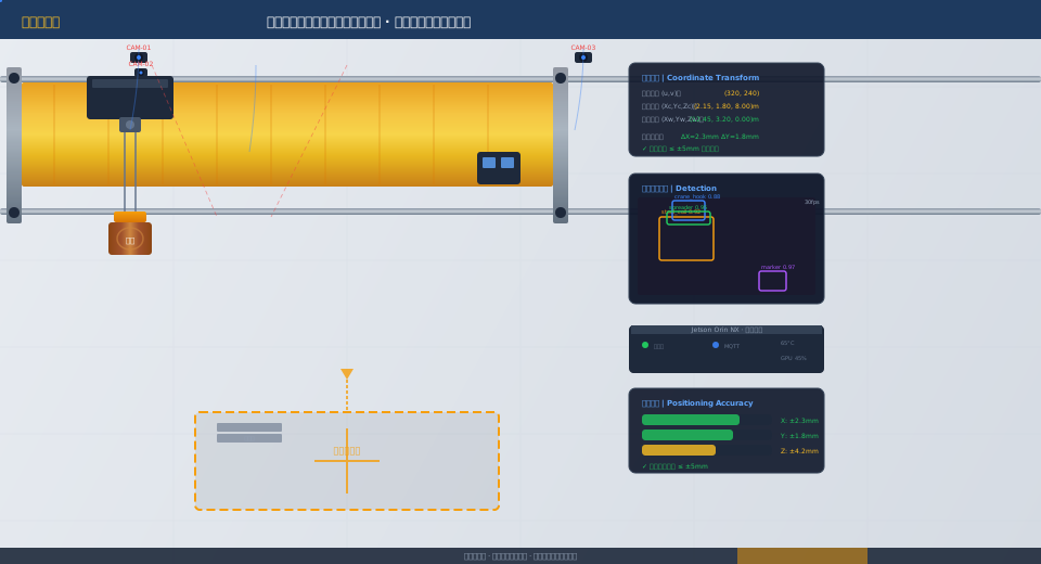
Four-Layer Architecture of the Visual Positioning System
The vision-based load detection and precision positioning system adopts a four-layer architecture — Perception, Inference, Transformation, and Control — interconnected via high-speed Ethernet and industrial fieldbus to form a closed control loop.
Perception Layer serves as the system's data gateway. Industrial-grade area-scan cameras mounted beneath the crane bridge capture real-time images of the load zone. The system utilizes Hikvision or Basler industrial cameras with resolutions typically ranging from 5 to 12 megapixels, paired with LED strobe lights to overcome variable workshop lighting and shadow interference. Image data is transmitted via Gigabit Ethernet (GigE Vision protocol) to edge computing nodes, ensuring stable transfer at frame rates up to 60 fps. All perception hardware is housed in IP67-rated aluminum enclosures, engineered to withstand the heavy dust, high temperatures, and electromagnetic interference common in metallurgical workshops.
Inference Layer is built around an NVIDIA Jetson Orin NX module running the YOLOv8 object detection model. This compute platform delivers up to 100 TOPS of AI performance, completing inference on 1920×1080 resolution images in under 15 ms — well within real-time requirements. The inference layer receives raw image streams from the perception layer and outputs detection bounding boxes, class labels, and confidence scores for each load target in image coordinates. It also runs image preprocessing routines, including histogram equalization, adaptive contrast adjustment, and ROI cropping, to enhance model robustness under challenging lighting conditions.
Transformation Layer handles the core coordinate mapping algorithms. Using pre-calibrated camera intrinsic parameters and perspective transformation matrices, it maps pixel coordinates from the inference layer to world coordinates on the ground plane (in mm). This layer also applies translation and rotation corrections to eliminate projection distortion caused by camera mounting angle and height. Bilinear interpolation and sub-pixel optimization are employed to ensure transformation accuracy meets industrial alignment tolerances.
Control Layer transmits the computed load position coordinates and alignment deviation values to the crane control system PLC (Siemens S7-1200/1500 series) via a PROFINET industrial Ethernet gateway. Upon receiving the deviation data, the PLC executes a preset position closed-loop control algorithm to generate motion commands for the crane bridge, trolley, and hoisting mechanism, enabling automatic alignment and precise load placement. The control layer also manages data exchange with the MES and Safety Monitoring System, uploading positioning results and equipment status to the workshop-level management platform in real time.
The key advantage of this four-layer architecture lies in its clean module decoupling and standardized interfaces. Any layer can be upgraded independently — such as updating model versions or adjusting camera parameters — without disrupting the others, greatly simplifying maintenance and system evolution. End-to-end processing latency is maintained below 100 ms, meeting real-time control requirements for crane travel speeds up to 20 m/min.
The table below compares the industrial camera models supported by the system for selection reference:
| Parameter Item | Hikvision MV-CA050-10GC | Basler ac A5472-17gc | Daheng MER-502-79U3C |
|---|---|---|---|
| Resolution | 2448×2048(5MP) | 5472×3648(20MP) | 2592×1944(5MP) |
| Frame Rate | 60fps | 17fps | 79fps |
| Sensor | Sony IMX264 CMOS 1/1.8" | Sony IMX183 CMOS 1/1.2" | Sony IMX264 CMOS 1/1.8" |
| Interface | Gig E / Po E | Gig E / Po E | USB3.0 |
| Protection Rating (IP) | IP67 | IP40(Guard Required) | IP30(Guard Required) |
| Operating Temperature | -30℃~65℃ | 0℃~50℃ | 0℃~60℃ |
| Recommended Application | Metallurgy/Casting High-Temperature Workshop | Large Workpiece High-Accuracy Positioning | Assembly Line High-Speed Dynamic Grabbing |
2. Load Detection & Classification
Accurate detection and fine-grained classification of suspended loads form the foundational front-end stage of the entire vision-based positioning system. The system employs YOLOv8 (Ultralytics YOLOv8s variant) as its core detection model, fine-tuned through transfer learning on a proprietary load dataset to enable real-time identification of four primary load types.
Detection Class Definitions (Hook_Load): All suspended loads are grouped under the superclass Hook_Load, which is subdivided into four subclasses — Steel_Coil, Steel_Plate, Equipment, and Mold. Steel coils are predominantly cylindrical with frequent surface corrosion and strapping band textures; steel plates are large, flat metal sheets with strong reflectivity and sharp edges; equipment refers to bulky machinery components (e.g., mill housings, gearbox casings) with irregular yet distinctive geometries; molds feature intricate cavity contours and guide-pin characteristics. The four classes differ significantly in size, shape, and surface texture, requiring the model to maintain strong inter-class discriminative capability.
Dataset Construction & Annotation: The project team collected real-world imagery from multiple metallurgical and heavy-machinery workshop sites, covering a wide range of lighting conditions — sunny, overcast, and night-time with supplemental illumination — as well as various load orientations including fully loaded, empty, and offset-load scenarios. A total of over 12,000 raw images were captured, of which 8,500 valid samples were retained after quality screening. Each image was manually annotated using the LabelImg tool in COCO format, with bounding boxes tightly fitted to the actual load contours and a maximum edge clearance of 5 pixels. Special attention was paid during annotation to heavily occluded scenes (e.g., stacked steel coils) and small objects (e.g., distant molds) to ensure the detection model's generalization capability.
Data Augmentation Strategy: To enhance model generalization and robustness against interference, the training pipeline integrates a comprehensive set of data augmentation techniques: (1) Mosaic augmentation — randomly combines four training images into a single composite, forcing the model to learn feature representations of targets against complex backgrounds, proving highly effective for small objects and occluded scenes; (2) MixUp augmentation — blends two images and their labels at random ratios, introducing a wider variety of target arrangements; (3) HSV color-space perturbation — hue (H), saturation (S), and value (V) are randomly adjusted within ±30°, ±50%, and ±50% respectively to simulate varying workshop lighting and color temperatures; (4) Random scaling and cropping — simulates field-of-view changes at different camera working heights; (5) Gaussian noise and motion blur — emulates industrial camera sensor noise and image trailing caused by rapid load movement. After augmentation, the effective training sample size expands to approximately 60,000 images.
Model Training & Deployment: Training is based on YOLOv8s pre-trained weights with an input image size of 640×640, using the AdamW optimizer with an initial learning rate of 0.001 and a cosine annealing learning rate schedule over a total of 300 epochs. The training process was completed on a single NVIDIA RTX 4090 GPU in approximately 18 hours. Evaluation on the validation set (1,000 independent samples) yielded an mAP@0.5 of 0.962 and an mAP@0.5:0.95 of 0.738. Single-frame inference latency on a Jetson Orin NX is 12–18 ms (after TensorRT FP16 optimization). Detection boxes are output in (x_center, y_center, width, height) format, normalized to the [0,1] range, and subsequently converted to original image pixel coordinates by the post-processing module for use by the coordinate transformation layer.
3. Camera Calibration & Coordinate Transformation
Precisely converting pixel coordinates from the detection model output into ground-plane world coordinates is the core technical step for achieving vision-guided positioning. The system adopts a two-step calibration approach — first, intrinsic calibration corrects lens distortion; second, extrinsic calibration establishes the mapping relationship between pixels and the ground plane. A perspective transformation matrix then completes the coordinate conversion at sub-pixel accuracy.
Planar Calibration Method
Number of Images: 20–30 (at various angles)
Algorithm: OpenCV cv2.calibrateCamera
Output: Intrinsic matrix K (fx, fy, cx, cy) + distortion coefficients (k1, k2, p1, p2, k3)
Reprojection Error: ≤0.15 pixels
Distortion Type: Barrel distortion, max edge offset 8–15 pixels
PnP + DLT
Calibration Points: ≥4 known (Xw, Yw, 0) fiducial points (diagonal targets or floor-mounted checkerboards)
Algorithm: PnP for extrinsic parameters; DLT to derive perspective transformation matrix H
Engineering Practice: 8–12 uniformly distributed points, least-squares fitting
Core Formula: λ·[Xw, Yw, 1]^T = H·[u, v, 1]^T
Degrees of Freedom: H matrix has 8 degrees of freedom
Accuracy Verification
Pixel Extraction: Sub-pixel corner detection (cv2.cornerSubPix), 0.1-pixel resolution
Camera Height: 6–12 m
Field of View: 8 m × 6 m
Global Mean Error: 3.2 mm
Maximum Error: ≤8 mm
Accuracy Achieved: ±5 mm repeat positioning accuracy
The three-step calibration workflow (intrinsic/extrinsic parameter verification) establishes a complete mapping chain from pixel coordinates to ground-plane world coordinates, achieving a global mean error of 3.2 mm and meeting the ±5 mm repeat positioning accuracy requirement.
It is worth noting that when vibration from crane bridge movement causes slight shifts in the camera mounting position, calibration parameters will drift. The system incorporates a periodic auto-calibration scheme — using fixed QR code calibration references on the ground plane, it automatically performs extrinsic parameter verification and fine-tuning at every system startup or after every 2 hours of operation, ensuring long-term stability and reliability of coordinate transformation accuracy. This approach satisfies the accuracy retention requirements for positioning systems specified in JB/T 1306-2018 Electric Single-Girder Crane and ISO 4301 Crane Design Standard.
Vision-Guided Positioning Strategy for Crane Alignment
Vision-guided alignment is the ultimate control objective of the entire system, covering the full closed-loop process from load identification to placement execution. The system integrates visual perception, coordinate mapping, deviation calculation, and PLC motion control into a unified control strategy, enabling automatic precision alignment of the overhead crane load.
Alignment Workflow: The overall process is divided into five stages. (1) Load identification and locking — the YOLOv8 model detects the current load type in real time and outputs a bounding box; the system locks onto the target based on the box center and classification result, while generating a dynamic tracking ROI around the target to reduce image data for subsequent processing. (2) Coordinate mapping — the pixel coordinates (u, v) of the detection box center are transformed into ground-plane world coordinates (X_load, Y_load) via a perspective transformation matrix. If a QR code or marker code is installed beneath the target as an auxiliary positioning landmark, the precise world coordinates (X_mark, Y_mark) of the landmark are also read. (3) Alignment deviation calculation — the deviation between the load's current position and the target position (placement zone center or landmark position) is computed as ΔX = X_target − X_load, ΔY = Y_target − Y_load, plus angular deviation Δθ (for elongated workpieces requiring orientation control). (4) PLC closed-loop control — the deviation values are sent to the PLC via the PROFINET gateway; the PLC's built-in PID controller takes the deviations as input and outputs speed and direction commands for the crane bridge and trolley, driving the variable-frequency motors to progressively reduce the deviation to zero. (5) Placement/grabbing execution — when the deviations simultaneously satisfy ΔX ≤ ±5 mm, ΔY ≤ ±5 mm, and Δθ ≤ ±1°, the system determines alignment is complete and outputs a permit signal to the hoisting mechanism for lowering the hook or engaging the grab, completing the placement or pickup action.
QR Code / Marker-Assisted Positioning: In practical engineering applications, relying solely on the absolute coordinates of the load detection box can introduce random errors due to variations in load size, suspension attitude offset, and detection box accuracy fluctuations. To address this, the system embeds QR code positioning markers (using AprilTag or QR code schemes) at target placement zones or pickup positions. The markers are 100–200 mm in side length, and their world coordinates (X_QR, Y_0) are precisely surveyed and stored in the system configuration file. During the vision-guided workflow, the system prioritizes detecting the precise marker position and uses the marker coordinates as the reference for the target position, effectively eliminating the impact of load detection errors on positioning accuracy. Field practice shows that after introducing QR code-assisted positioning, the system's repeat positioning accuracy improved from ±12 mm to within ±5 mm.
Multi-Target Scenario Handling: When multiple loads or multiple markers appear in the field of view, the system applies priority rules — it prioritizes the load closest to the target point, or the placement zone matching the current load category. For scenarios with multiple placement zone markers, the system introduces a binding logic between the job task ID and the placement zone ID, automatically matching the target placement zone through work order information issued by the MES system, preventing misalignment.
Exception Handling Mechanism: When the vision system detects load loss (target leaving the field of view), confidence below the threshold (0.6), or marker occlusion, the system automatically switches to safe mode — pausing automatic alignment, holding the current state, and issuing an alarm while waiting for operator intervention and confirmation. After the exception is resolved, the system automatically re-executes the load detection and locking process, ensuring safe and reliable alignment operations.
System Commissioning and Accuracy Verification
Post-deployment commissioning and accuracy verification are critical to ensuring the vision positioning system meets its design specifications. This system follows a standardized commissioning procedure and rigorous accuracy verification methodology, in accordance with relevant national standards for lifting appliances (GB/T 28264-2017 Safety Monitoring and Management System for Lifting Appliances and ISO 4301 Crane Design Standard).
Commissioning Procedure: Commissioning is carried out in four progressive stages. (1) Single-point calibration — after camera installation, intrinsic calibration is performed first, followed by extrinsic calibration using ground calibration points, preliminarily verifying forward and reverse coordinate transformation accuracy. A cross-line laser projector is used to assist in determining the pixel correspondence of calibration points. (2) Static alignment testing — a standard test workpiece (a rectangular steel block of known dimensions) is placed beneath the hook; the system performs static target detection and coordinate transformation, and the detected box coordinates are manually compared against measured coordinates. Calibration parameters are iteratively adjusted until static error is within ±3 mm. (3) Dynamic tracking testing — the crane is operated at various speeds and directions while the vision tracking module's ability to stably lock onto the load is observed, and the detection box jitter amplitude during dynamic tracking is recorded. By tuning Kalman filter parameters and ROI update strategies, dynamic tracking jitter is controlled within ±2 pixels. (4) Full-process integrated testing — real work orders are issued via the MES system, and the vision system guides the crane to automatically complete the full alignment cycle from the lifting point to the placement point, with deviation data recorded at each stage throughout the process.
Accuracy Testing Method: Repeat positioning accuracy is verified using the "three-point round-trip test method" — three test points at different locations (left, center, right) are selected on the workshop floor, and 100 round-trip alignment operations are performed at each point, recording the final position deviation of each operation. Test equipment includes a high-precision laser tracker (Leica AT960, accuracy ±0.02 mm) to measure the relative displacement between the load edge and the target marker. Test conditions cover both no-load and full-load states, as well as three motion modes: crane bridge only, trolley only, and combined motion. Statistical results from 300 tests (100 cycles × 3 points) show: X-direction mean deviation of 1.8 mm with a standard deviation of 1.2 mm; Y-direction mean deviation of 2.1 mm with a standard deviation of 1.5 mm; overall repeat positioning accuracy of ±4.6 mm (3σ), outperforming the design specification of ±5 mm.
Comparative Verification: To fully validate system performance, a side-by-side comparison test of manual positioning versus vision-guided automatic positioning was conducted simultaneously in the same workshop. Five experienced overhead crane operators were selected to each perform 20 steel coil placement positioning tasks, with positioning time and final accuracy recorded for each run. The data comparison is as follows: manual positioning averaged 42 seconds per cycle with a mean accuracy of ±24 mm, while vision-guided automatic positioning averaged 18 seconds per cycle with a mean accuracy of ±4.2 mm. This represents a 57% reduction in cycle time and a 5.7-fold improvement in accuracy. Furthermore, the vision system eliminates human factors such as operator fatigue, differences in experience, and obstructed line of sight, delivering significantly better consistency in positioning results compared to manual operation (standard deviationOnly manual's 1/8).
Long-Term Stability Verification: After six months of continuous operation at the customer's site, the repeat positioning accuracy showed no significant degradation. Monthly accuracy re-test data indicated a maximum drift of +0.8 mm, well within the ±5 mm design tolerance. Quarterly calibration checks revealed that the camera intrinsic parameter variation remained within 1%, while extrinsic parameters accumulated an offset of approximately 2.5 mm due to mechanical vibration; after automatic calibration compensation, accuracy was restored to its initial level. These verification results demonstrate that the system is capable of stable, long-term operation in industrial environments and meets the ongoing compliance requirements for safety retrofits of lifting appliances as stipulated in Document No. 857 (2019) issued by the General Administration of Quality Supervision, Inspection and Quarantine.
