

AI Vision Inspection for Crane Wire Rope Defects
AI-Powered Visual Inspection System for Crane Wire Ropes: Deep Learning-Based Detection of Broken Wires, Wear, and Corrosion. The wire rope is the most critical load-bearing component of an overhead crane, and its condition directly impacts equipment safety and operational continuity.
The wire rope is the most critical load-bearing component of an overhead crane, and its health directly affects equipment safety and production uptime. Traditional manual inspection—relying on visual checks and handheld gauges—suffers from blind spots, subjective judgment, and an inability to provide real-time warnings. With the maturation of deep learning, AI vision-based online wire rope inspection has become a key enabler of digital transformation across the industry. This article draws on an actual deployment by Kelude Heavy Industry to present the overall architecture, core algorithms, hardware setup, and engineering practices of an AI visual inspection system for crane wire ropes.
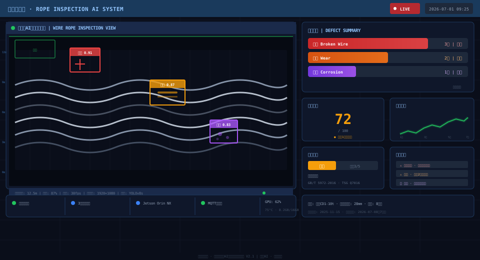
System Architecture for Real-Time Wire Rope Inspection
The AI visual inspection system for crane wire ropes uses a four-layer architecture that forms a closed loop from raw data acquisition to business-level integration, ensuring real-time performance, accuracy, and full traceability of inspection results.
1. Sensing Layer (Image Acquisition)
The sensing layer forms the foundation of the system, comprising high-resolution industrial cameras, LED strobe illumination, and optical lenses. Depending on the rope section and inspection requirements, a multi-camera deployment strategy is used: top-down cameras cover the fixed-end zone at the upper section, side-mounted cameras monitor the free rope length in the middle, and bottom-up cameras target the lower rope end and the hook block sheave area. Each camera is equipped with a global-shutter CMOS sensor supporting frame rates up to 200 fps, enabling clear capture of microscopic surface defects while the crane is in motion. The LED strobes operate in pulsed mode with pulse widths adjustable down to the microsecond level, effectively overcoming oil reflection and uneven lighting for consistent image quality.
2. Inference Layer (AI Computing Platform)
The inference layer runs on NVIDIA Jetson edge computing devices, executing an improved YOLOv8s object detection model. The model is optimized and accelerated with the TensorRT inference engine, achieving a single-frame inference time of under 25 ms—sufficient for real-time detection at a rope travel speed of 0.5 m/s. This layer performs defect detection on every frame, outputting bounding box coordinates, class confidence scores, and segmentation masks for broken wires, wear, corrosion, and other defects. Raw detection results and feature vectors are simultaneously uploaded to the analysis layer.
3. Analysis Layer (Defect Classification and Assessment)
The analysis layer runs on the server side, receiving detection results from the inference layer and performing fine-grained classification on each detected region using a dedicated defect classification model. Built on an EfficientNet-B4 backbone, the model distinguishes 11 sub-types of wire rope defects: localized broken wires, concentrated broken wires, uniform wear, localized wear, pitting corrosion, uniform corrosion, wavy deformation, lantern deformation, rope diameter reduction, insufficient lubrication, and surface contamination. The analysis layer also fuses time-series data to track multiple detection results at the same location over time, assessing defect progression trends and severity grades.
Assessment results from the analysis layer are categorized into four severity grades: Normal (Grade 0), Mild (Grade 1), Moderate (Grade 2), and Severe (Grade 3). When the defect grade reaches Moderate or above, the system automatically triggers the alarm mechanism.
4. Alarm Layer (PHM and Maintenance Integration)
The alarm layer is deeply integrated with the Predictive Health Management (PHM) platform and the Computerized Maintenance Management System (CMMS). When a wire rope defect reaches the alarm threshold, the system automatically performs the following actions: (1) displays a real-time alarm pop-up on the PHM dashboard, highlighting the defect location and type; (2) generates a standardized maintenance work order based on defect grade and location, and pushes it to the CMMS; (3) notifies the responsible maintenance personnel via SMS, WeChat, or email; and (4) records the full context of the alarm event—including defect images, timestamps, equipment ID, and operating conditions—for post-event traceability. The average response time from detection to work order generation is under 30 seconds.
| Hierarchy | Function Module | Core Equipment/Algorithm | Critical Indicator |
|---|---|---|---|
| Perception Layer | Image Acquisition and Preprocessing | Global Shutterindustrial camera, LEDStrobe Lighting | Resolution≥1920×1080, Frame Rate≥100fps |
| Inference Layer | Edge Real-time Inference | YOLOv8s + Tensor RT, Jetson Orin NX | Inference Latency≤25ms, Detection Frequency≥40FPS |
| Analysis Layer | Defect Classification and Trend Assessment | Efficient Net-B4, Temporal Tracking Algorithm | Classification Accuracy≥95%, Trend Prediction Error≤10% |
| Alarm Layer | Alarm Push and Maintenance Integration | PHMPlatform, CMMSInterface, Message Push | Alarm Response≤30s, False Alarm Rate≤5% |
2. Wire Rope Defect Types and AI Detection Methods
During long-term service, overhead crane wire ropes are subjected to combined effects of alternating stress, friction wear, corrosive environments, and fatigue loads, resulting in various types of damage. In accordance with ISO 4309 (Cranes — Wire ropes — Care and maintenance, inspection and discard), wire ropes require periodic inspection with systematic recording of all defect types. A vision inspection system must reliably identify the following primary defect categories.
1. Wire Fracture Detection
Wire fracture is the most common and hazardous defect type, classified by distribution pattern into localized broken wires and concentrated broken wires. Scattered fractures occur at various positions along the rope length, typically caused by localized overload or wire fatigue; in early stages, the fracture ends are minute and difficult to detect with the naked eye. Localized fractures refer to multiple wires breaking near the same cross-section, usually resulting from mechanical damage or severe overload, with jagged, saw-tooth fracture ends. The AI detection system enhances the C2f feature extraction module in the improved YOLOv8s model by incorporating deformable convolution (DCNv4) and coordinate attention mechanisms, enabling the model to focus on subtle texture differences in fracture zones. Within the feature pyramid network, the model fuses shallow high-resolution features with deep semantic features, ensuring that small-scale wire fracture targets are not lost during feature downsampling.
2. Wear Defect Identification
Wear is categorized into uniform wear and localized wear. Uniform wear manifests as a consistent reduction in wire rope diameter along its entire length, with surface wires flattened — typically caused by prolonged friction against pulleys and drums. Localized wear appears as a noticeable diameter reduction in specific rope segments or flattened grooves on the surface, often resulting from rope-to-rope friction or interference with structural components. When detecting wear defects, the AI model leverages both gradient features from the wire rope contour edges and surface texture features. The model incorporates an additional diameter regression branch in the head module, directly outputting estimated rope diameter values within each detection region. These values are compared against historical inspection data to enable quantitative wear measurement, with measurement error controlled within 0.3 mm.
3. Corrosion Defect Recognition
Corrosion defects are particularly prevalent in overhead crane wire ropes operating in high-humidity, high-corrosion environments such as metallurgical plants, chemical facilities, and ports. Early-stage corrosion appears as pitting rust spots on the surface, progressing to flaking and pit corrosion as deterioration advances; in severe cases, the effective cross-sectional area of the wire is significantly reduced. In imaging, corrosion defects present as color-anomalous regions (reddish-brown, dark black) with uneven surface texture characteristics. The AI detection model employs a multispectral fusion strategy, combining RGB images with near-infrared channel imagery at the feature level. This approach leverages the high reflectivity of corrosion byproducts in the near-infrared band to enhance contrast in corrosion-affected areas. Experimental results demonstrate that the multispectral fusion strategy improves corrosion defect detection recall by 12.7%.
4. Deformation Defect Detection
Wire rope deformation defects include wavy deformation and lantern deformation. Wavy deformation refers to a sinusoidal bending of the rope axis, typically caused by sudden unloading or kinking, which accelerates wire fatigue fracture during subsequent operation. Birdcage deformation manifests as a localized increase in rope diameter with strands spreading outward in a cage-like pattern — an external indication of internal wire breakage or core failure. While the visual characteristics of deformation defects are relatively distinct, their morphological variation is extensive, placing high demands on model generalization capability. To enhance deformation detection robustness, the system applies large-scale affine transformation augmentation to deformation samples during training, including random rotation (−45° to 45°), random scaling (0.5× to 1.5×), and elastic deformation simulation, enabling the model to adapt effectively to diverse deformation patterns.
| Defect Category | Sub-type | Visual Features | Detection Challenges | Improvement Strategy |
|---|---|---|---|---|
| Wire Break | Localized Wire Break, Concentrated Wire Break | Bright White Reflective Fracture Surface, Wire Fracture End Face | Small Fracture Size(0.5-2mm), Strong Background Interference | Feasible Deformation Convolution+Attention Mechanism |
| Wear | Uniform Wear, Localized Wear | Rope Diameter Reduction, Surface Flattening, Loss of Metallic Luster | Requires Quantitative Measurement Wear Requires Quantitative Measurement, High Sensitivity to Lighting | Diameter Regression Branch+obturator Gradient Features |
| Corrosion | Pitting Corrosion, Uniform Corrosion | Reddish-brown Rust Spots, Flaking, Surface Irregularity | Color Features Easily Confused with Oil Stains | Multispectral Feature Fusion |
| Deformation | Wavy Deformation, Lantern-shaped Deformation | Axis Bending, Localized Diameter Enlargement, Strand Splaying | Wide Range of Morphological Variations, Scarce Samples | Affine Transformation+Elasticity Deformation Augmentation |
3. Image Acquisition System Design
The image acquisition system serves as the "eyes" of AI visual inspection, and its design quality directly determines the detection performance of downstream models. Overhead crane wire ropes operate in demanding environments subject to intense lighting, oil contamination, vibration, and dust—all of which place stringent requirements on the imaging system. This system is engineered across three dimensions: camera deployment architecture, optical component selection, and illumination strategy.
1. Three-Camera Collaborative Deployment
Based on the geometric characteristics and motion profile of the crane wire rope, the system employs a three-camera collaborative imaging scheme to achieve full-length coverage with no blind spots:
Inspection Zone: First set of pulleys from the drum exit
Sensor: Line-scan CMOS (8192×1, 80kHz line rate)
Speed Matching: Encoder-synchronized equidistant acquisition
Detection Focus: Broken wires, wear, corrosion; also monitors spooling alignment
Advantage: Fixed trajectory enables continuous high-resolution imaging
Inspection Zone: Mid-section free rope length
Sensor: Area-scan global shutter CMOS (1920×1080, 200fps)
Lens: Wide field of view to accommodate lateral rope swing
Detection Focus: Wear distribution across full length, wave deformation, lubrication condition
Advantage: Global shutter eliminates motion distortion; wide coverage
Inspection Zone: Lower rope section + hook block sheave area
Sensor: Area-scan global shutter CMOS (1920×1080, 200fps)
Protection: Compact design with automatic air purge to prevent oil buildup
Detection Focus: Broken wires and wear in bending zones (high-incidence area)
Advantage: Targets high-defect region without interfering with hook movement
2. Camera Selection and Optical Parameters
Camera selection was based on a comprehensive evaluation of resolution, frame rate, shutter type, light sensitivity, and Protection Rating (IP). The top-down camera uses a line-scan CMOS sensor with a resolution of 8192×1 pixels and a maximum line rate of 80kHz, synchronized with the encoder to achieve equidistant acquisition matched to rope speed. The side-view and bottom-up cameras employ 2MP area-scan global shutter sensors with a resolution of 1920×1080 and a maximum frame rate of 200fps. Global shutter technology ensures that high-speed rope movement does not produce the image distortion or motion blur associated with rolling shutter effects. All cameras feature industrial-grade IP67-rated housings with built-in heaters and defogging functionality, enabling reliable operation across a wide working environment range of -20°C to 60°C.
3. Strobe LED Lighting and Anti-Interference Design
Crane wire ropes are typically coated with lubricating oil and grease, which produce strong specular reflections under conventional lighting and severely degrade image quality. The system employs a strobe LED illumination scheme with pulse widths controlled within the 10–50 microsecond range, precisely synchronized with the camera exposure timing. The strobe mode delivers high-intensity illumination in an extremely short window, reducing reflective glare to tiny bright spots rather than large bloom areas while substantially suppressing ambient light interference. The lighting fixture uses a ring configuration uniformly distributed around the lens optical axis, ensuring even illumination across the full circumference of the wire rope. For color temperature, 5000K–6000K neutral white light is selected to match the spectral response peak of the industrial camera sensor, maximizing photoelectric conversion efficiency.
| Camera ID | Deployment Location | Sensor Sub-type | Resolution | Frame Rate/Line Rate | Detection Section |
|---|---|---|---|---|---|
| Camera 1 | Trolley Platform Top-down View | Line Scan CMOS | 8192×1 | 80kHz | Upper Rope Section(Drumto First Pulley) |
| Camera 2 | End Carriage Side View | Area Scan Global Shutter CMOS | 1920×1080 | 200fps | Middle Free Rope Length Zone |
| Camera 3 | Hook Upward View from Below | Area Scan Global Shutter CMOS | 1920×1080 | 200fps | Lower Rope Section+hook block sheave |
4. Model Training and Dataset
A high-quality dataset and a well-structured training strategy form the foundation of any AI-based detection model's performance. This system establishes a complete workflow across data collection, annotation, and training to ensure strong detection accuracy and generalization capability.
1. Dataset Construction
Over 10,000 wire rope images were collected from active production sites, covering four defect categories—broken wires, wear, corrosion, and deformation—along with normal rope samples. All images were captured under real operating conditions of overhead cranes, including varying lighting (overcast, sunny, and nighttime with supplemental lighting), different operating states (stationary, low-speed running, and rated-speed running), and multiple load conditions (empty, half-load, and full load). To increase sample diversity, the dataset also incorporates field data from five different steel plants and ports, spanning rope diameters from 16 mm to 48 mm and various rope constructions (6×19, 6×37, 8×19, etc.).
2. Data Annotation
Annotations follow the COCO dataset format, with each image paired with a JSON annotation file. Each annotation includes the defect class label, polygon bounding box coordinates, and a defect segmentation mask. Annotation work is performed by trained quality inspection engineers, and every annotation is cross-reviewed by senior experts to maintain an accuracy rate of no less than 98%. Ambiguous samples—such as borderline cases between slight wear and normal surface texture—are resolved through team discussion and physical comparison to establish consistent labeling standards. The final dataset contains 11 target classes with the following sample distribution: localized broken wires (1,200 images), concentrated broken wires (800), uniform wear (1,500), localized wear (1,000), pitting corrosion (1,200), uniform corrosion (800), wavy deformation (400), lantern-shaped deformation (300), rope diameter reduction (600), poor lubrication (900), and normal samples (1,300).
3. Data Augmentation
To improve model generalization and robustness, a comprehensive set of data augmentation strategies is applied during training: (1) Geometric transformations—random rotation (−30° to 30°), horizontal and vertical flipping, random cropping, and scaling (0.5× to 1.5×); (2) Color adjustments—brightness (±20%), contrast (±15%), saturation (±10%), and hue shift (±5°); (3) Noise injection—Gaussian noise (σ = 5–15) and salt-and-pepper noise (density 0.01–0.03); (4) Blur simulation—Gaussian blur (kernel size 3–7) and motion blur to mimic rope movement trails; (5) Occlusion simulation—Random Erasing and CutOut to replicate oil-contamination scenarios. These augmentation techniques effectively expand the training sample size by more than 20×, significantly improving detection performance under complex operating conditions.
4. Training Configuration and Process
The model is trained on the YOLOv8s architecture with input images uniformly resized to 640×640 pixels. Key hyperparameters are configured as follows: SGD with momentum (momentum = 0.937) as the optimizer, an initial learning rate of 0.01 with a cosine annealing schedule, a weight decay coefficient of 0.0005, a batch size of 32, and 300 training epochs. A warm-up strategy is employed, with the learning rate linearly increasing from 0.001 to the initial rate over the first 3 epochs. Early stopping is enabled, terminating training automatically if validation mAP shows no improvement for 30 consecutive epochs. Training converges in approximately 24 hours on a single NVIDIA RTX 4090 GPU, with final training loss dropping below 1.2 and validation mAP meeting the design target.
5. Detection Performance and Maintenance Integration
Following deployment and continuous optimization, the AI-based online wire rope detection system for overhead cranes meets engineering application standards across all key performance indicators. The system is also deeply integrated with the equipment maintenance management framework, forming a complete closed loop of detection, assessment, alerting, and maintenance.
1. Detection Performance Metrics
The detection performance metrics on the system's dedicated test set (2,000 images, independent of the training and validation sets) are presented in the table below. All metrics were measured on the Jetson Orin NX Edge Computing device, with inference throughput consistently exceeding 40 FPS—sufficient for real-time detection of crane wire rope moving at speeds up to 0.5 m/s.
| Defect Category | m AP@0.5 | m AP@0.5:0.95 | Precision | Recall | F1-Score |
|---|---|---|---|---|---|
| Wire Break Detection | 0.93 | 0.72 | 0.91 | 0.88 | 0.89 |
| Wear Detection | 0.89 | 0.65 | 0.87 | 0.83 | 0.85 |
| Corrosion Detection | 0.85 | 0.59 | 0.84 | 0.80 | 0.82 |
| Deformation Detection | 0.82 | 0.56 | 0.80 | 0.76 | 0.78 |
| Composite Detection | ≥0.93 | ≥0.70 | ≥0.85 | ≥0.82 | ≥0.84 |
2. Integration with CMMS Maintenance Systems
The system connects to an existing Computerized Maintenance Management System (CMMS) through standard RESTful API interfaces. When the AI detection system identifies wire rope defects that reach a preset alarm level, the following integration workflow is triggered automatically: (1) retrieving equipment master data, maintenance history, and spare parts inventory from the CMMS; (2) matching maintenance recommendations and discard criteria based on defect type and severity level, in accordance with GB/T 5972-2016; (3) generating a standardized maintenance work order that includes equipment ID, defect location (identified by rope length offset), defect images, severity level, recommended actions, and priority tags; (4) pushing the work order to the CMMS and assigning it to the designated trade and maintenance crew; (5) after the work order is completed, maintenance personnel feed back the resolution results, and the system re-captures post-repair wire rope images for inclusion in the model's continuous learning loop. The entire integration process—from detection to work order dispatch—averages under 30 seconds, enabling closed-loop management from problem identification to resolution.
3. Compliance with National Standards
The system's detection criteria and discard determination strategy fully reference the following national standards: GB/T 5972-2016 Cranes — Wire ropes — Care, maintenance, inspection and discard defines the methods, frequency, and discard criteria for daily wire rope inspection and serves as the core basis for the system's detection judgments; ISO 4301 Crane design standard specifies safety factor requirements for wire rope selection and design; and TSG Q7016-2016 Supervision regulations on inspection of installation, retrofit and major repair of lifting appliances sets forth compliance requirements for lifting appliance inspection and testing. The system embeds a digitalized rules engine for each standard, automatically matching applicable standard clauses during result determination to ensure that maintenance recommendations and alarm levels are fully compliant.
Frequently Asked Questions
Q: Can AI vision detection fully replace manual inspections?
A: AI vision detection serves as a powerful complement to manual inspections, but it cannot fully replace them at the current stage. Per GB/T 5972-2016, periodic inspections of wire ropes must be carried out by trained, dedicated inspection personnel. The AI vision system enables 24/7 continuous monitoring and achieves a detection rate of over 90% for typical defects such as broken wires, wear, and corrosion. However, defects that cannot be assessed from surface images—such as internal broken wires or core condition—still require electromagnetic testing (EMT) or manual tactile inspection. The recommended maintenance model is "AI online monitoring plus periodic manual re-inspection": the AI system handles high-frequency, full-coverage daily screening, while human inspectors perform in-depth periodic re-checks and confirm anomalies.
Q: How much do oil contamination and lighting variations affect detection accuracy?
A: Oil contamination and lighting variation are among the greatest engineering challenges for AI-based wire rope vision detection. The system mitigates environmental interference through three measures: first, strobed LED fill lighting provides controlled high-intensity illumination within microsecond intervals, reducing the relative impact of ambient light; second, the training dataset includes a large number of negative samples with oil coverage and varying lighting conditions, improving model robustness against interference; third, adaptive histogram equalization and Retinex illumination correction algorithms are applied during image preprocessing. In field tests, detection accuracy drops by no more than 2 percentage points when oil contamination covers less than 30% of the rope surface. When oil coverage is severe (>50%), the system automatically flags the affected image segment as "review restricted" and prompts manual re-inspection.
Q: Does the system's detection accuracy meet national standard requirements?
A: The system's detection accuracy is designed to fully align with national standard requirements. GB/T 5972-2016 specifies wire rope discard criteria including: number of broken wires in one lay length reaching 10% of the total wire count, diameter wear or corrosion reaching 7% of the nominal diameter, and conditions such as lantern deformation or core protrusion. The system achieves an mAP of ≥0.93 for broken wire detection, rope diameter measurement error of ≤0.3 mm, and corrosion area detection error of ≤5%. The system also incorporates a compliance checking engine for ISO 4301 and TSG Q7016-2016, which outputs the specific standard clause numbers used when automatically determining a discard conclusion. The system is periodically calibrated by third-party metrology certification bodies to ensure traceability of detection results.
Q: How does the system ensure long-term stability and maintainability?
A: The system ensures long-term stable operation across three dimensions: hardware, software, and data. On the hardware side, all field devices feature industrial-grade protective design (IP67 protection rating, wide operating temperature range, vibration-resistant mounting), and critical components use redundant configurations. On the software side, the system includes a built-in self-diagnosis module that periodically checks camera image quality (focus sharpness, exposure level, frame rate consistency), inference engine status, and network connection quality, automatically raising alarms and attempting self-recovery when anomalies are detected. On the data side, the system implements a continual learning mechanism: high-confidence detection results are automatically selected weekly and, after human review, incorporated into the incremental training dataset. A model fine-tuning update is performed quarterly, enabling the model to adapt to changing wire rope wear patterns and emerging defect types. The system also provides a remote operation and maintenance management platform that supports over-the-air firmware and model upgrades, reducing on-site maintenance costs.
Kelude Heavy Industry is a professional manufacturer of industrial cranes and hoists, offering a comprehensive range of material handling solutions for demanding applications across manufacturing, logistics, and process industries.
Industrial Crane Types and Applications
Our product lineup covers single-girder and double-girder overhead cranes, gantry cranes, and jib cranes, each engineered to meet specific load and span requirements. From 1-ton workshop cranes to 100-ton heavy-duty process cranes, we deliver reliable performance in the most challenging environments.
| Crane Type | Capacity Range | Typical Application |
| Single-Girder Overhead Crane | 1 – 20 t | Maintenance, assembly, light fabrication |
| Double-Girder Overhead Crane | 5 – 100 t | Heavy machining, steel coil handling, foundry |
| Gantry Crane | 3 – 50 t | Outdoor yards, precast concrete, container handling |
| Jib Crane | 0.25 – 5 t | Workstation lifting, machine loading |
Electric Wire Rope Hoists for Precise Lifting
Kelude electric wire rope hoists are designed for smooth, precise load positioning and long service life. Available in single-speed and two-speed versions, these hoists feature a compact low-headroom design that maximizes usable lifting height in low-ceiling facilities.
Standard safety features include overload protection, limit switches on both hoist and trolley travel, and a self-locking brake system that holds the load securely in the event of a power failure. All hoists are factory-tested and certified to ISO 4301 design standards.
Explosion-Proof Cranes for Hazardous Areas
For facilities handling flammable gases, vapors, or combustible dust, Kelude offers explosion-proof cranes and hoists rated for Zone 1 and Zone 2 hazardous areas. These units feature sealed electrical enclosures, anti-sparking components, and specially coated surfaces to eliminate ignition risks.
Explosion-proof packages are available on all crane types and can be customized to meet ATEX or IECEx certification requirements, depending on your regional compliance needs.
Anti-Sway Technology for Safer Load Control
Our advanced anti-sway control system uses closed-loop feedback from encoders on the hoist and trolley drives to actively dampen load swing during travel. This technology reduces operator fatigue, shortens cycle times, and improves positioning accuracy—especially important when handling fragile or high-value loads.
The system is available as an option on double-girder cranes and can be retrofitted to existing equipment during modernization projects.
Crane Components and Aftermarket Support
Beyond complete crane systems, Kelude supplies a full range of replacement components, including crane wheels, end carriages, festoon systems, and radio remote controls. Our aftermarket team provides spare parts, preventive maintenance programs, and on-site repair services to keep your equipment running at peak efficiency.
Frequently Asked Questions
Q: What is the lead time for a standard overhead crane?
A: Typical lead time for a standard single-girder crane is 4–6 weeks from order confirmation. Double-girder and custom-engineered cranes typically require 8–12 weeks, depending on configuration and options.
Q: Do you provide installation and commissioning services?
A: Yes, our service engineers can supervise or perform the complete installation and commissioning on-site. We also offer operator training and maintenance documentation in English.
Q: Can your cranes be designed to meet specific local codes?
A: Absolutely. Our cranes are designed in accordance with ISO 4301 and IEC 60204-32, and we can adapt designs to comply with local regulations and site-specific requirements, including seismic zones and outdoor wind loads.
Q: What warranty do you offer on crane equipment?
A: All Kelude cranes come with a 12-month warranty covering defects in materials and workmanship. Extended warranty and preventive maintenance contracts are available upon request.
