

Crane Bridge Travel Resistance: Friction, Wind & Slope Loads
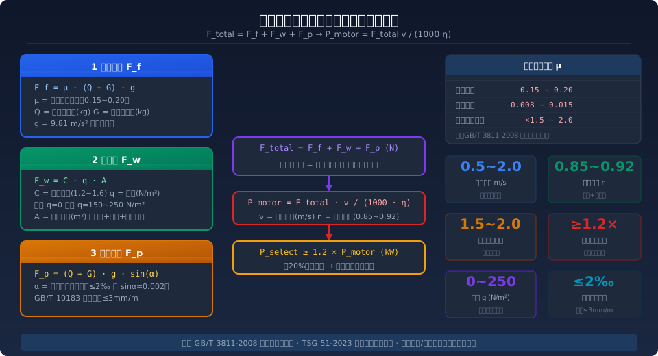
The total travel resistance of a crane bridge is the sum of three components: friction resistance (F_f), wind resistance (F_w), and slope resistance (F_p). The core calculation formula is F_total = μ·(Q+G)·g + C·q·A + (Q+G)·g·sin(α). The required drive motor power is P ≥ 1.2·F_total·v/(1000·η). For standard overhead cranes, the travel motor power typically ranges from 0.8 to 7.5 kW.
The bridge travel mechanism is the drive system that moves bridge cranes and gantry cranes longitudinally along the crane rail. Accurate travel resistance calculation is critical for selecting the right motor power, matching the gearbox speed ratio, and sizing the power supply circuit. Underestimating the resistance leads to frequent motor overload trips; overestimating it results in inefficient light-load operation and wasted procurement costs. This article provides a systematic breakdown of the three resistance components, their parameter selection criteria, and a quick-reference engineering selection table to give designers a complete calculation framework. Kelude Heavy Industry has extensive engineering experience in crane travel drive systems—from measuring wheel block friction coefficients to verifying motor power, from controlling rail installation accuracy to tuning frequency inverter parameters—offering full-process technical support.
Friction Resistance: Formula and Coefficient Selection
Friction resistance is the dominant component of bridge travel resistance, comprising wheel rolling friction and bearing friction. The general formula is: F_f = μ · (Q + G) · g, where μ is the combined friction coefficient, Q is the rated lifting capacity (kg), G is the crane dead weight (kg), and g = 9.81 m/s². This formula follows the "running resistance under steady motion" calculation method specified in Clause 5.2.3 of ISO 4301 Crane Design Standard, applicable to the rolling contact condition between the wheel tread and the top surface of the crane rail.
The combined friction coefficient μ depends on the bearing type used in the wheel block: for plain bearings, μ = 0.15–0.20; for rolling bearings, μ = 0.008–0.015. Note that these values represent the pure rolling friction coefficient of the wheel. In actual engineering calculations, an additional wheel flange friction factor of 1.5–2.0 must be applied (i.e., μ_actual = μ × 1.5–2.0) to account for the extra friction generated when the wheel flange rubs against the rail side due to skewing. For cranes with a span greater than 22.5 m or where the two sides of the bridge travel out of synchronization, the upper limit of 2.0 is recommended for the flange friction factor.
Wind Resistance: Calculation and Operating Condition Assessment
Wind resistance F_w is considered only for outdoor operation or indoor environments with cross-drafts; for enclosed workshops, F_w = 0. The formula is F_w = C · q · A, where C is the wind force coefficient (1.2–1.6, depending on the structural cross-section shape), q is the design wind pressure (N/m²), and A is the projected area of the crane structure perpendicular to the wind direction (m²). For bridge cranes, this area is the sum of the main girder side projection, the end carriage projection, and the hoisting mechanism's windward area.
The wind pressure q follows the altitude-dependent wind pressure coefficients in Annex E of ISO 4301: for inland areas, the working-condition design wind pressure is 150 N/m²; for coastal areas, it is 250 N/m². For non-working conditions (strong winds with the crane out of service), wind pressure can reach 600–800 N/m², in which case the anchoring force of the anti-wind anti-slip device must be verified rather than the drive power. For gantry cranes, the large windward area (main girder + legs + trolley) means wind resistance can account for 30%–50% of total resistance—this cannot be ignored.
Slope Resistance and Rail Installation Accuracy
Slope resistance F_p arises from the longitudinal gradient of the crane rail during installation. Even with standard installation practices, rails cannot be perfectly level. The formula is F_p = (Q + G) · g · sin(α), where α is the longitudinal slope angle of the rail. When the gradient is ≤2‰ (i.e., a height difference of ≤2 mm per meter), sin(α) ≈ 0.002, and the slope resistance approximates F_p ≈ (Q + G) · g × 0.002. GB/T 10183-2005 Bridge and Gantry Crane Manufacturing and Rail Installation Tolerances specifies a maximum single-rail slope deviation of 3 mm/m and a maximum height difference of 10 mm per 10 m between the two rails.
For general purpose bridge cranes with work duty classification A4 to A5, the rail gradient typically falls within 0.5‰–1.5‰, and slope resistance accounts for 3%–8% of total travel resistance. However, for gantry cranes—especially large-span MG type units—where the two rails are laid on separate ground foundations, differential foundation settlement can create localized gradients of 2‰–3‰ in service, pushing the slope resistance share to 10%–15%. Design selection should comply with the travel mechanism safety factor requirements of TSG 51-2023 Crane Safety Technical Supervision Regulation. It is recommended that gantry crane motor power be verified against a 2‰ gradient to ensure adequate safety margin.
Total Travel Resistance and Drive Power Calculation
The total travel resistance F_total is the sum of the three components: F_total = F_f + F_w + F_p (in N). The most unfavorable combination is assumed—i.e., full load, headwind, and uphill gradient occurring simultaneously. In practice, the wind resistance term is zero for indoor cranes; for mixed indoor/outdoor applications, only the full-load-plus-uphill condition needs to be considered.
The drive motor power is calculated as: P_motor = F_total · v / (1000 · η), where v is the long-travel speed (m/s; typically 0.5–2.0 m/s for standard overhead cranes) and η is the overall drive train efficiency (including gearbox, coupling, and bearings; typically 0.85–0.92). For selection purposes, P_select ≥ 1.2 × P_motor, applying a 20% safety margin to cover the additional inertial load during acceleration. The final motor power is rounded up to the nearest standard power rating (0.75/1.1/1.5/2.2/3.0/4.0/5.5/7.5 kW, etc.).
| Lifting Capacity (t) | Dead Weight Approx. (t) | travel speed (m/s) | F_f (k N) | F_total (k N) | P_motor (k W) | Recommended Motor (k W) |
|---|---|---|---|---|---|---|
| 5 | 4.5 | 0.5 | 1.86 | 2.05 | 1.14 | 1.5 |
| 10 | 7.0 | 0.5 | 3.34 | 3.67 | 2.04 | 2.2 |
| 16 | 10.5 | 0.67 | 5.19 | 5.72 | 4.26 | 5.5 |
| 20 | 13.5 | 0.67 | 6.56 | 7.22 | 5.37 | 7.5 |
| 32 | 20.0 | 0.83 | 10.19 | 11.21 | 10.33 | 11.0(Dual Motor) |
| 50 | 32.0 | 0.83 | 16.07 | 17.68 | 16.29 | 7.5kW×2 |
Note: Ff in the table already includes a wheel flange additional coefficient of 1.8; indoor conditions Fw=0; rail slope calculated at 1‰. Cranes above 50t use dual-side independent drive (dual motor + dual gearbox).
Engineering Calculation Example: 16t Bridge Crane Travel Power Verification
Using a QD Type 16t electric double-girder bridge crane as a complete calculation example. Known conditions: Q=16000kg, G=10500kg, travel speed v=0.67m/s (40m/min), wheels equipped with rolling bearings (μ=0.012), wheel flange additional coefficient of 1.8, indoor workshop (Fw=0), rail slope 1‰ (sinα≈0.001), transmission efficiency η=0.88.
Step-by-step calculation process:
① Friction resistance Ff = 0.012 × 1.8 × (16000+10500) × 9.81 = 0.0216 × 26500 × 9.81 ≈ 5615N
② Grade resistance Fp = 26500 × 9.81 × 0.001 ≈ 260N
③ Total resistance Ftotal = 5615 + 260 = 5875N
④ Motor power Pmotor = 5875 × 0.67 / (1000 × 0.88) ≈ 4.47kW
⑤ Applying a 1.2× safety factor Pselect = 1.2 × 4.47 ≈ 5.36kW, rounded up to the next standard motor rating of 5.5kW
Conclusion: A 5.5kW motor meets the design requirements for the 16t bridge crane travel mechanism. In this case, Kelude's engineering team also verified the VFD capacity during the design review (recommending a 7.5kW VFD paired with the 5.5kW motor) to ensure sufficient torque margin during the acceleration phase.
Six-Step Method for Selecting Crane Bridge Travel Drive Power
- Step 1: Identify the bearing type — Check the wheel block drawings to determine whether plain bearings or rolling bearings are used. Rolling bearings use μ=0.01–0.015; plain bearings use μ=0.15–0.20. For the same load capacity, the rolling bearing configuration requires only 1/10 to 1/15 of the motor power needed for plain bearings — the preferred choice.
- Step 2: Calculate the combined friction coefficient — Multiply the rolling/plain friction coefficient by the wheel flange additional coefficient of 1.5–2.0. Use 1.5 for spans ≤16.5m, 2.0 for spans ≥22.5m, and interpolate linearly in between.
- Step 3: Determine the wind load condition — Indoor installations: Fw=0. Outdoor or semi-open installations: calculate at 150N/m² for inland sites or 250N/m² for coastal sites. Cranes positioned near doorways must additionally account for cross-draft wind loads (crosswind).
- Step 4: Verify the rail slope — Calculate the grade resistance using the measured slope or the design value (typically 0.5‰–1.5‰). For gantry cranes, verify at 2‰.
- Step 5: Calculate Pmotor by summing all resistance components — Apply the formula Pmotor = (Ff+Fw+Fp)·v / (1000·η) to obtain the theoretical power requirement.
- Step 6: Apply the safety margin and round up — Pselect ≥ 1.2×Pmotor, rounded up to the nearest standard power rating. For ratings ≥22kW, consider a dual-motor dual-side drive configuration.
| Parameter | Symbol | Unit | Range | Value Description |
|---|---|---|---|---|
| Friction Coefficient(Rolling) | μ_roll | - | 0.008~0.015 | Rolling Bearing Wheel Block |
| Friction Coefficient(Sliding) | μ_slide | - | 0.15~0.20 | Plain Bearing(Legacy Equipment) |
| Wheel flange Additional Coefficient | k_rim | - | 1.5~2.0 | Span>22.5mUse Upper Limit |
| Wind Force Coefficient | C | - | 1.2~1.6 | Box girder Take1.5~1.6 |
| Wind Pressure(Inland) | q | N/m² | 150 | ISO 4301 Crane Design Standard Working Condition |
| Wind Pressure(Coastal) | q | N/m² | 250 | ISO 4301 Crane Design Standard Working Condition |
| Transmission Efficiency | η | - | 0.85~0.92 | Gear+Coupling Drive Train |
| Power Safety factor | k_s | - | ≥1.2 | Covered Startinertia load |
Related Reading: After sizing the bridge travel mechanism motor, you'll typically need to match the VFD parameters — see Crane VFD Self-Tuning Procedure: Full Motor Parameter Identification and PI Auto-Tuning Guide. For travel mechanism bearing selection, refer to How to Choose the Crane Pulley Block Ratio: Calculation Formulas and Engineering Selection Reference Table.
Frequently Asked Questions
Q: What motor size is typically used for the bridge travel on a 5t overhead crane?
A: For a 5t LD-type electric single-girder bridge crane with a dead weight of approximately 4.5t and rolling bearings (μ = 0.01–0.012), the friction resistance at a travel speed of 0.5 m/s is about 1.86 kN. This yields P_motor ≈ 1.14 kW; applying a 1.2 safety factor gives a 1.5 kW standard motor. If plain bearings are used (older designs), μ rises to 0.15–0.20, requiring a 7–10 kW motor — which is why rolling bearings are strongly recommended for new designs.
Q: Why does a gantry crane require significantly more power than an overhead crane of the same capacity?
A: Three factors explain the difference. First, a gantry crane has a much larger wind-exposed area due to its outrigger structure, so outdoor wind resistance F_w accounts for 30%–50% of total resistance, whereas indoor overhead cranes see F_w = 0. Second, gantry cranes typically use plain-bearing wheel blocks (μ = 0.15–0.20), giving a combined friction coefficient 10–15 times higher than the rolling bearings used on overhead cranes. Third, outdoor rails are subject to foundation settlement, with actual gradients reaching 2‰–3‰, compared to 0.5‰–1‰ indoors. Combined, these factors mean a gantry crane of the same capacity needs roughly 3–5 times the power of an overhead crane.
Q: What happens if the bridge drive motor is undersized?
A: An undersized motor typically causes the following problems in service: ① the VFD trips on overcurrent protection (OL2 alarm) or the thermal overload relay opens during full-load starting; ② sustained overload operation pushes winding temperature beyond the 130°C limit for Class B insulation, accelerating insulation aging and cutting service life to 30%–50% of rated life; ③ insufficient torque at low-speed creeping causes stepwise jerking, subjecting wheels and rails to periodic impact loads that accelerate fatigue spalling on the wheel tread. Occasional overload trips can be compensated by adjusting the VFD torque boost parameters, but persistent overload requires replacing the motor with the next size up.
Q: Can the bridge travel mechanism use dual-motor drive? How is power distributed?
A: Yes — dual-motor drive is standard on overhead cranes above 32t and on most gantry cranes. The dual-motor configuration uses a symmetrical layout with one motor and gearbox at each end, each rated at 50%–55% of total power (accounting for a 1.1 load-sharing imbalance factor). The advantages are: elimination of torsional vibration and shaft alignment issues from long drive shafts; if one motor fails, the other can return the crane to the maintenance bay at low speed; and cross-communication between the two VFDs provides electronic synchronization, replacing the mechanical rigid synchronous shaft.
Kelude Heavy Industry Technical Recommendation: Bridge travel mechanism design and selection require coordinated expertise across mechanical, electrical, and civil engineering disciplines. Kelude Heavy Industry has extensive engineering experience in travel drive systems for both overhead and gantry cranes, offering complete technical services covering wheel block selection, motor power calculation, VFD parameter configuration, and crane rail foundation design. For technical consultation: 400-086-9590.
