

Crane VFD Auto-Tuning: Motor Parameter & PI Identification
VFD auto-tuning is the process by which the drive's built-in algorithm automatically identifies motor parameters such as stator resistance, mutual inductance, and inertia, and completes automatic PI regulator tuning. It is a critical step in commissioning a crane's inverter drive system, directly determining hoisting smoothness and positioning accuracy.
The quality of crane drive system commissioning directly affects operational efficiency and safety. Kelude's technical team has found through years of field commissioning that traditional parameter setting relies heavily on the engineer's experience—manually entering nameplate data and then iteratively adjusting PI gains through trial and error is time-consuming and inconsistent. With the widespread adoption of Vector Control and Direct Torque Control (DTC), mainstream drives (ABB ACS880, Siemens S120, Inovance MD880, etc.) now integrate an auto-tuning function module that can automatically identify motor parameters and tune PI regulators within 30 seconds to 5 minutes. This article systematically outlines the standard operating procedures and common troubleshooting methods for crane VFD auto-tuning, based on the requirements of ISO 4301 Crane Design Standard and GB/T 12668 Variable Frequency Speed Control Technical Specification.
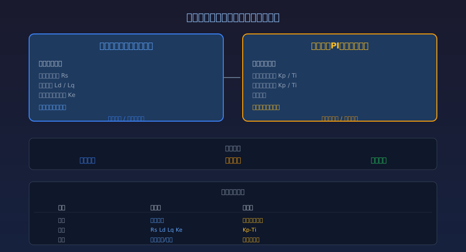
Level 1—Motor parameter identification. Test signals are injected to measure physical parameters such as winding resistance, inductance, and back-EMF constant, establishing an accurate motor mathematical model.
Level 2—PI regulator auto-tuning. Based on the identified motor model, the drive automatically calculates speed-loop and current-loop PI parameters to ensure fast yet stable dynamic response. Both levels can be executed independently or automatically in sequence.
Why VFD Auto-Tuning Matters for Crane Hoisting Performance
The core objective of VFD auto-tuning is to build a mathematical model that closely matches the actual motor. In Vector Control (VC) mode, the drive performs real-time coordinate transformations (Clarke and Park transforms) to decompose the three-phase current into magnetizing current component id and torque current component iq, achieving decoupled control similar to a DC motor. This process relies heavily on the accuracy of the following motor parameters:
Stator resistance Rs: Affects voltage compensation accuracy in the low-speed region. For crane hoisting mechanisms, torque ripple during low-speed heavy-load operation is positively correlated with Rs error—a deviation exceeding 20% can cause noticeable vibration at hoist start-up.
Mutual inductance Lm and leakage inductance Lσ: Determine the accuracy of the flux observer. Mutual inductance error directly impacts rotational speed estimation accuracy at low speeds in sensorless Vector Control (SLVC) mode. Typical crane drives require Lm identification error to be kept within ±5%.
Moment of inertia J: Influences the calculation of speed-loop PI parameters. Crane load inertia varies over an extremely wide range (empty hook vs. full load can differ by 10–50 times). The motor's inherent inertia Jm obtained through auto-tuning serves as the baseline reference for all subsequent PI calculations.
Auto-tuning is especially required in the following scenarios: first-time power-up commissioning (first pairing of motor and drive), after replacing the motor or drive (rebuilding the mathematical model), after more than 6 months of operation (motor parameters drift due to temperature rise and aging), and when low-speed vibration or positioning overshoot occurs (suspected PI parameter mismatch). IEC 60204-32 Machinery Electrical Safety Standard also explicitly requires that drive parameters be set based on the actual characteristics of the controlled motor, not merely inferred from nameplate data.
Static vs. Rotating Auto-Tuning: Which to Choose
Motor parameter auto-tuning is available in two modes—Static Auto-Tuning and Rotating Auto-Tuning—and the choice depends on the application scenario and mechanical connection status:
Static Auto-Tuning (Static ID Run)—The drive injects pulse-width modulation (PWM) test signals into the motor and measures stator resistance Rs, leakage inductance Lσ, and mutual inductance Lm without rotating the motor shaft. The motor remains stationary throughout the process, which typically takes 30–120 seconds. This mode is suitable for scenarios where the motor is already coupled to mechanical loads such as reducers or drums and cannot be decoupled (e.g., an installed crane hoisting mechanism), as well as for initial position identification of Permanent Magnet Synchronous Motors (PMSM). The limitation is that moment of inertia J and back-EMF constant Ke cannot be measured and must still be entered manually from nameplate data.
Rotating Auto-Tuning (Rotating ID Run)—The drive rotates the motor at a certain speed (typically 50%–80% of rated speed) and measures all motor parameters during rotation, including moment of inertia J. The process takes approximately 2–5 minutes. This mode offers the highest parameter accuracy, with Rs and Lm identification errors controllable within ±3% and J identification error around ±10%. It is suitable for scenarios where the motor shaft can be decoupled from the load (e.g., during commissioning or standalone motor testing), or when the hoisting mechanism's dual-brake design allows the coupling to be safely disengaged.
| Comparison Item | Stationary Auto-tuning | Rotation Stationary Auto-tuning | Recommended Application |
|---|---|---|---|
| Motor Rotation Required | No(Stationary) | Yes(50%~80%Rated Rotational speed) | Depending on Machinery Conditions |
| Identification Parameter | Rs, Lσ, Lm | Rs, Lσ, Lm, J, Ke | Required JOptional Rotation |
| RsIdentification Accuracy | ±5%~10% | ±2%~5% | Select for Low-Speed Heavy Load Rotation |
| Duration | 30~120Seconds | 2~5Minutes | Minimize On-site Time |
| Machinery Decoupling Requirement | Not Required | Required(or with Safety Measures) | Hoisting mechanism Stationary Preferred |
| Applicable Motor Type | Asynchronous/Permanent magnet Synchronization | asynchronous motor(PMSMTo be Confirmed) | Asynchronous Recommended Rotation |
For typical hoisting mechanism duty cycles, the following strategy is recommended: during initial commissioning, if safety conditions permit disconnecting the coupling, prioritize rotational auto-tuning to capture complete motor parameters; if the mechanical system is already connected and cannot be easily decoupled, use static auto-tuning combined with manual entry of nameplate data. Since the inertia variation for the crane bridge and trolley travel mechanisms is relatively small, static auto-tuning is generally sufficient to meet accuracy requirements.
PI Regulator Auto-Tuning: Speed Loop and Current Loop Parameter Calculation
Once motor parameter identification is complete, the VFD automatically proceeds to the PI auto-tuning stage, calculating the PI parameters for the speed loop and current loop. This process is mathematically based on pole-zero cancellation and the symmetrical optimum method:
Current Loop PI Parameters: The current loop bandwidth is designed to be 1/10 to 1/20 of the switching frequency (typically 500–1000 Hz). The proportional gain Kp_current = Lσ × ωc (where ωc is the designed current loop crossover frequency), and the integral time Ti_current = Lσ / Rs (i.e., the motor's electrical time constant). Current loop auto-tuning can be completed during the static auto-tuning phase without rotating the motor. For PMSM motors, the current loop also requires additional calculation of the cross-decoupling coefficients for the d-axis and q-axis inductances.
Speed Loop PI Parameters: The speed loop bandwidth is typically designed to be 1/5 to 1/10 of the current loop bandwidth (typically 50–150 Hz). The proportional gain Kp_speed = J × ωsc / Kt (where J is the total system inertia, ωsc is the designed speed loop crossover frequency, and Kt is the motor torque constant), and the integral time Ti_speed = 4 / ωsc. Speed loop auto-tuning requires the inertia value J; if static auto-tuning was used and J was not obtained, it must be entered manually or the rotational auto-tuning mode should be selected.
In crane applications, PI auto-tuning involves several special considerations: the hoisting mechanism operates in a regenerative state during full-load lowering, which can cause the DC bus voltage to rise rapidly. The brake chopper activation threshold must therefore be verified separately after PI auto-tuning. The mechanical drive train of the crane bridge travel mechanism (gearbox + wheels + rail) introduces significant backlash and elasticity, resulting in anti-resonance peaks in the frequency response. In this case, a notch filter should be added on top of the speed loop PI to suppress mechanical resonance in specific frequency bands.
Standard Commissioning Procedure: 5 Steps to Complete Auto-Tuning
The following is the standard 5-step auto-tuning procedure for crane VFDs, applicable to vector control VFDs from major brands:
Step 1: Verify Wiring and Safety Conditions — Confirm that the VFD output terminals U/V/W are correctly connected to the motor's three phases, and that the PE grounding wire is securely connected (grounding resistance ≤ 4 Ω). Verify that the braking resistor (if fitted) is connected and has the correct resistance value. For the hoisting mechanism, ensure the brake is in the closed position (mechanical brake application) to prevent accidental load slipping during auto-tuning. For the bridge and trolley travel mechanisms, confirm the travel path is clear of obstructions.
Step 2: Enter Motor Nameplate Parameters — Accurately enter the motor nameplate ratings in the VFD parameter group: rated power PN (kW), rated voltage UN (V), rated current IN (A), rated frequency fN (Hz), rated speed nN (rpm), and number of pole pairs p. These parameters serve as the initial reference values for the auto-tuning algorithm. Input deviations exceeding 10% may cause auto-tuning to fail or converge to incorrect values.
Step 3: Select Auto-Tuning Mode and Start — Based on the mechanical connection status, select static auto-tuning (e.g., ABB parameter 99.09 = Static ID Run, Inovance F1-37 = 1) or rotational auto-tuning (99.09 = Rotating ID Run, F1-37 = 2). Once started, the VFD automatically executes the following sequence: DC injection to measure stator resistance → high-frequency signal injection to measure leakage inductance → ramp excitation to measure mutual inductance → (in rotational mode) acceleration to target speed to measure back-EMF and inertia. The progress percentage (0–100%) can be observed on the display screen throughout the process, and the VFD automatically stops output upon completion.
Step 4: Verify Identification Results — After auto-tuning is complete, navigate to the parameter view page and check the deviation between the identified values and the motor nameplate values: Rs deviation should be within ±15% (exceeding this indicates excessive wiring resistance or inter-turn short circuits in the motor winding); Lm deviation should be within ±20% (exceeding this may indicate a motor type mismatch, such as a two-speed motor configured as single-speed); the no-load current I0 should be within 30%–50% of the nameplate rated current. If any parameter is clearly abnormal, repeat the auto-tuning process.
Step 5: Perform PI Auto-Tuning and Test Run — After motor parameter identification passes, execute the PI auto-tuning function (e.g., ABB Speed Loop Autotune, Inovance F1-38 = 1). Once complete, perform a low-speed (5–10 Hz) jog mode test run to observe whether the motor runs smoothly and without abnormal vibration or noise. Gradually accelerate to rated frequency and check that the three-phase currents are balanced (imbalance < 5%). For the hoisting mechanism, verify hoisting and lowering smoothness under both no-load and rated load conditions.
Self-Learning Failure: Common Causes & Troubleshooting
| Fault Symptom | Possible Cause | Troubleshooting Method | Recommended Solution |
|---|---|---|---|
| Reports"Motor ID Run Failed" | motor wiring Error/Phase Loss/Nameplate Parameter Deviation Excessive | multimeter Measure Phase by Phase Resistance, Three-Phase Resistance Imbalance<3% | Correct Wiring and Re-run |
| RsIdentification Value Abnormally High | Frequency Inverter / VFDtomotor cable Too Long/Terminal Block Oxidation | Measure Cable Resistance, Cable Resistance> Motor Rsof10%Indicates Abnormality | Increase Cross-Section Cableor Shorten Distance; Clean Terminals |
| Rotation Stationary Auto-tuning Motor Trips on Start | Brake Not Fully Open/Machinery Seized/Overcurrent Protection Value Too Low | Manual Bar Rotor to Confirm Free Rotation; Check Brake Clearance | Repair Brake; Temporarily Increase Overcurrent Protection Value |
| Auto-tuning Passed but Operation Unstable | PIParameter Default Values Mismatched/Machinery Resonance Not Suppressed | Start Button Feedback Spectrum Analysis, Locate Resonance Frequency | Manual Fine-tune PIParameter; Add Notch Filter |
| Inconsistent Identification Results | Motor Large Temperature Variation/Power Supply Voltage Fluctuation/Electromagnetic Interference | Measure Once in Cold and Hot State, Compare Deviation | Use Hot State(Operation30min After)Result as Reference |
| PMSMRotation Auto-tuning Reports"Overcurrent" | Permanent magnet Rotor Initial Position Identification Failed/Back Electric EMF Too High | To be Confirmed Motor Pole Pairs and Back Electric EMF Constant KeInput Correctly | Run Stationary Auto-tuning First to Confirm Initial Position |
Crane-Specific VFD Commissioning: Key Adjustments
Commissioning a VFD for crane duty differs from general industrial drives in several important ways. Beyond the standard auto-tuning routine, the following points require special attention:
Zero-Speed Holding for the Hoisting Mechanism — After auto-tuning is complete, verify the hoist drive's zero-speed holding capability. In sensorless vector control (SLVC) mode, the VFD must deliver sufficient excitation current at 0 Hz to generate holding torque. A successful tuning result should prevent noticeable load drift (angular deviation <5°) when the brake is released, under both empty-hook and full-load conditions. If drift occurs, manually increase the IR compensation voltage in the low-speed range (0–3 Hz).
Master-Slave Control for the Crane Travel Mechanism — When the double-girder crane travel mechanism uses master-slave control, each VFD must be auto-tuned individually. Never copy identification parameters from one drive to the other. Manufacturing tolerances between the two motors can cause Rs deviations of 3%–5%; sharing parameters leads to uneven load distribution (when output torque deviation between the two motors exceeds 10%, one motor becomes chronically overloaded). We recommend completing separate auto-tuning for each drive, then enabling the load-sharing function.
Braking Unit Coordination — During rotational auto-tuning, the motor may enter regenerative mode (during deceleration). Confirm that the braking chopper's DC bus overvoltage protection threshold matches the deceleration ramp time used in the tuning sequence. We suggest temporarily extending the deceleration time to 10 seconds or more before tuning, to prevent DC bus overvoltage from triggering a fault shutdown that interrupts the procedure.
In practice, the quality of VFD drive system commissioning directly determines the operational stability of the equipment after handover. Kelude has extensive commissioning experience in variable-frequency drive systems for overhead, gantry, and metallurgical cranes. Every overhead crane we deliver undergoes auto-tuning and verification according to the standard procedures described above, and we provide customers with complete parameter backup files and commissioning reports. For project-specific VFD selection and commissioning support, contact the Kelude technical service team at 400-086-9590.
Related reading: Hoisting Mechanism Selection in Four Steps — Complete Calculation Guide for Motor, Gearbox, Drum, and Brake | Electric Hoist Motor Overheating? 5 Common Causes and Step-by-Step Fixes
Frequently Asked Questions
Q: What quantitative accuracy requirements does IEC 60204-32 specify for auto-tuning?
A: Under vector control mode, the standard requires motor parameter identification to stay within defined relative error limits: stator resistance Rs ≤ ±10%, mutual inductance Lm ≤ ±15%, and moment of inertia J ≤ ±20%. These accuracy indicators directly affect the speed control accuracy (SCA) classification. For crane applications requiring high positioning accuracy, rotational auto-tuning is recommended to achieve higher parameter identification precision.
Q: Can the speed loop PI parameters auto-tuned on a hoist drive be used directly?
A: The typical speed loop bandwidth for a hoisting mechanism is 50–100 Hz, and auto-tuning results are generally usable as-is. However, the system inertia under full load is significantly higher than the no-load inertia during tuning. We recommend increasing the proportional gain Kp by 10%–20% after auto-tuning to compensate for load inertia variation. The acceptance standard should be a smooth motor current waveform under full-load hoisting, with no low-frequency oscillation (≤5 Hz).
Q: Is auto-tuning required every time a motor is replaced? Can nameplate parameters be entered manually instead?
A: Auto-tuning must be re-run after every motor replacement, even if the replacement is the same model. Motors from the same batch can have 5%–10% manufacturing tolerance in winding parameters, and manual nameplate entry cannot reflect the actual resistance and inductance values of the installed winding. If site conditions prevent rotational auto-tuning, at minimum static auto-tuning must be completed. Skipping the tuning step entirely and relying on nameplate data is not acceptable.
Q: When multiple cranes use the same VFD and motor models, can I auto-tune one unit and copy the parameters to the others?
A: Direct parameter copying is not recommended. Even with identical motor models, each winding has a normal manufacturing deviation of 3%–7% in resistance and inductance. Combined with differences in cable length and terminal contact resistance, copied parameters can cause substandard low-speed control performance on some units. Each drive should be auto-tuned individually, and its own parameter set saved.
Kelude — Crane VFD Drive System Commissioning & Technical Support
