

Electric Hoist Runway Rail Selection & Installation
📋 Key Summary
Selecting and installing the runway rail for an electric hoist comes down to two things: matching the I-beam specification to the trolley wheel base, and controlling rail straightness and joint gaps at acceptance. An undersized I-beam lets the wheel flange bite into the web plate. Welding joints rigid causes expansion stress. Excessive straightness deviation accelerates wheel-rail wear. This article covers prerequisites, I-beam matching, the step-by-step construction process, and common mistakes to correct — giving you practical selection criteria and acceptance tolerances, all governed by the relevant standards and design drawings, so you can hold the line at handover acceptance.
Every electric hoist — from a hand chain hoist to a motorized trolley — ultimately hangs on an I-beam. In early workshops, hoists were either fixed under a beam for single-point lifting or pushed along a rail by hand. Once the electric trolley arrived, the hoisting mechanism and travel mechanism were combined into one unit that runs automatically along the lower flange of the I-beam. That is when the I-beam stopped being just a structural shape and became the runway for an entire lifting system.
Yet the selection and installation of this runway is precisely the most underestimated part of any electric hoist installation project. An undersized I-beam lets the trolley wheel flange bite into the web plate. A poorly treated rail joint delivers an impact every time the trolley passes over it. Excessive straightness deviation causes wheel and rail to wear against each other at a rate invisible to the eye. These problems may not show up at handover acceptance, but they tend to surface within six to eighteen months of operation. That is why Kelude Heavy Industry lists rail verification as a separate quality hold point in European standard electric hoist supporting projects.
Prerequisites to Verify Before Installing an Electric Hoist Runway
Installing a runway rail may look like simply hoisting an I-beam into place, but three prerequisites must be checked before any work begins. Skip any one of them, and the leveling and alignment work downstream will have to be redone.
① Load-bearing structure: The I-beam rail is suspended from roof truss beams or concrete beams via hanger plates and connection plates. The beam's load-bearing capacity and connection nodes must be confirmed by design — never drill or weld based on field judgment alone.
② Factory building clearance: The height of the rail's lower flange above the floor must satisfy the maximum lifting height required for the load, while also leaving room for the hoist body and future maintenance.
③ Power supply routing: The electric trolley travels along the rail, and the power supply method (trailing cable or conductor rail / busbar) directly determines the rail routing and the layout of support hangers. This must be confirmed in coordination with the electrical works.
Once these three items are verified, cross-check the section on tolerances for wheel and rail installation in ISO 12488-1 Overhead and Gantry Cranes — Tolerances for Wheel and Rail Installation to lock in the acceptance tolerances for rail straightness, elevation, and joints in advance. At Kelude Heavy Industry's pre-construction briefing, these tolerances are written into the construction record item by item as the basis for subsequent acceptance.
Matching I-Beam Specifications to Trolley Wheel Base
The starting point for determining I-beam specifications is the matching relationship between the trolley wheel tread and the I-beam's lower flange width — not a simple rule that a larger capacity means a larger beam.
The electric hoist trolley straddles the lower flange of the I-beam. The wheel tread rolls on the upper surface of the lower flange, while the wheel flanges grip both sides. The lower flange width must therefore match the wheel base. Too narrow, and the wheel flange rides off the flange edge. Too wide, and the wheel cannot press firmly, reducing the contact area. Typical matching ranges: a 1-ton hoist pairs with I16 to I20 I-beams, 3-ton with I25 to I28, 5-ton with I28a to I36a, and 10-ton with I32 to I45. The exact model also depends on span and lifting height.
The technical director at Kelude Heavy Industry pointed out: "A larger I-beam model is not always better. Go too large and the lower flange is too wide — the wheel tread cannot press firmly and wheel-rail contact actually gets worse. Go too small and the wheel flange bites into the web plate, and it wears out before long."
Beyond wheel base matching, the I-beam must also be checked for deflection and strength. Under rated lifting capacity, the mid-span deflection of a single-rail suspended I-beam must not exceed the allowable value, and local stresses in the web plate and flange must stay within limits. This follows the stiffness and strength calculation methods in FEM 1.001 Crane Design Standard, while EN 14492-1:2019 Wire Rope Electric Hoist specifies the technical requirements for the hoist body itself. Together, they form the complete basis for selection.
Step-by-Step Runway Rail Installation: Hoisting, Leveling, and Joints
Runway rail installation for an electric hoist typically proceeds in four steps, each with its own quality hold point.
Step 1 — Hoisting and positioning. Individual I-beam sections are lifted to near the design elevation using rigging, then temporarily fixed. Lifting points must be confirmed by design to prevent irreversible deformation during hoisting.
Step 2 — Leveling and alignment. Use a laser level instrument to measure the elevation of each support point, and a tensioned steel wire with a steel ruler to measure straightness in the horizontal plane. Adjust elevation and straightness to within acceptance tolerances by adding or removing shims.
Step 3 — Joint connection. Align adjacent I-beam sections first, then connect. Control the joint gap and misalignment. When welding, allow for expansion, and perform visual inspection after welding.
Step 4 — Trial run. After the rail is installed, run the electric trolley under no load first. Check for even wheel-rail contact and any impact when passing over joints. Once confirmed, proceed to under-load testing.
Kelude Heavy Industry's installation crew sets a mandatory quality hold point at Step 3: no welding or tightening is allowed until joint misalignment has been ground to the required value. This step may seem slow, but it saves the cost of rework and long-term wheel-rail wear down the road.
Runway Rail Installation Tool Checklist
| Tools/Instruments | Primary Application | Specificationoraccuracy requirements | Quantity | Remarks |
|---|---|---|---|---|
| LaserLevel Instrument | Rail ElevationandLevelnessDetection | Accuracynot less than0.02mm/m | 1unit(s) | requiredCalibrationQualified |
| steel coilRuler/Steel Straight Ruler | Track Gauge / Rail Gauge、joint gapMeasurement | Graduation Value1mm | each1pc(s) | Steel straight ruler used forJoint |
| feeler gauge | joint misalignmentand gap feeler gauge measurement | 0.02~1.0mmCombination | 1set(s) | piece-by-piece feeler gauge measurement |
| torque wrench | Connection bolttightening torquecontrol system | Measuring RangecoverageM12~M20 | 1pc(s) | per drawingTorque |
| Hand chain hoist/Hoistingsling | I-Beamlifting and positioning | Lifting Capacitygreater than single sectionCrane RailDead Weight | 1~2set(s) | Lifting pointafterdesign confirmation |
Most Common Electric Hoist Runway Rail Installation Mistakes: Welded Joints and Straightness Failures
Most rail installation mistakes aren't caused by technical difficulty — they come from making assumptions in the field. The three errors below are the most common on-site, and they carry the highest rework costs.
Mistake #1: Welding joints solid. A Runway Rail expands and contracts along its length as temperature changes. When joints are rigidly welded, there's no room for thermal expansion and contraction to release. Stress from temperature swings accumulates in the Weld Seam or the rail body itself, and over time the joint cracks and the rail deforms.
Mistake #2: Accepting out-of-tolerance Straightness as "good enough." Excessive straightness deviation causes the Trolley to sway side to side during traveling. The Wheel flange continuously bites into the side of the rail. It may look functional, but you're trading wheel-and-rail service life for short-term convenience.
Mistake #3: Using an undersized I-Beam anyway. When the Specification is insufficient, the lower flange Deflection under prolonged overload, and the Wheel flange grinds into the Web plate. Trying to mask this with extra Lubrication only makes it worse over time.
What these three mistakes share is that problems don't show up immediately — the installation may even pass Acceptance — but the cost comes back with interest after commissioning. At Kelude Heavy Industry, we've made these items mandatory inspection points during Acceptance specifically to catch hidden risks before the crane leaves our facility.
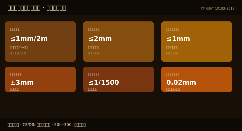
Rail Installation Acceptance Standard (per ISO 12488-1; for monorail systems, refer to the design drawing)
| inspection items | permissible deviationorrequirements | test method | determination |
|---|---|---|---|
| rail straightness(in horizontal plane) | per2mnot greater than1mm | pullSteel wire+Steel Straight Ruler | out of toleranceadjustmentre-measure after |
| Rail ElevationDeviation | between adjacent support points±3mm | LaserLevel Instrument | level by adding shims if out of tolerance |
| rail joint gap | Weldingconnection allowance≤2mm | feeler gauge | repair weld or grind if out of tolerance |
| Rail JointMisalignment | top surface/side surface≤1mm | Steel Straight Ruler+feeler gauge | grind to align if out of tolerance |
| Crane Raillongitudinal slope | not greater than1/1500 | LaserLevel Instrumentfull-length measurement | out of toleranceadjustmentsupport(s)Lifting point |
| Jointweld quality | NoneCrack、incomplete penetration、Slag Inclusion | Visual Inspection+if necessaryFlaw detection | Defectafter repair weldingre-inspection |
📖 Related reading: How to troubleshoot rail gnawing and travel deviation on an electric hoist | How to adjust the brake on an electric hoist
FAQ
Q: What does ISO 12488-1 specify for the straightness and joint gap of an electric hoist runway rail?
A: ISO 12488-1 covers installation tolerances for crane wheels and rails on overhead and gantry cranes. For monorail electric hoists, straightness and joint requirements are usually derived from the same order of magnitude but tightened further. Typical field control values are: straightness in the horizontal plane no greater than 1 mm per 2 m (0.04 in per 6.6 ft), a welded joint gap of roughly 2 mm (0.08 in), and joint misalignment no greater than 1 mm (0.04 in). Actual values must follow the design drawings and the manufacturer's installation manual, since they vary with lifting capacity and span.
Q: What size I-beam is typically used as the runway rail for a 5-ton electric hoist?
A: For a 5-ton electric hoist runway, common field practice is to use an I-beam from I28a to I36a, depending on the trolley wheel base, span, and lifting height. A wider wheel base and a longer span call for a larger beam. The size should not be decided by rule of thumb but calculated from the matching relationship between wheel tread width and the flange width of the I-beam's lower flange, with the final choice confirmed by design verification.
Q: How can I tell if the I-beam for an electric hoist runway is undersized?
A: The most direct sign of an undersized I-beam is the wheel flange rubbing continuously against the web plate during trolley travel, producing a metallic scraping sound and bright wear marks on the inside of the web. On closer inspection, noticeable deflection or localized deformation of the lower flange after prolonged operation is an early warning of insufficient load-bearing capacity. If any of these signs appear, stop the hoist immediately and recheck the I-beam specification and deflection check results — do not simply add more lubrication to mask the problem.
Q: Why must runway rail joints be left with a gap instead of being fully welded?
A: A runway rail expands and contracts lengthwise with temperature changes. If joints are rigidly welded shut, the thermal expansion has nowhere to release, generating tensile stress in the weld seam or the rail itself. Over time this can lead to joint cracking or rail deformation. Long rails therefore need expansion joints designed in, and even short rails or welded connections must have their joint gap and misalignment controlled so that expansion stress has a path to release.
Kelude Heavy Industry specializes in high-end customization of CE and DIN European Standard cranes. The matching European Standard Wire Rope Electric Hoist, runway rail selection, installation, and acceptance are handled as one package, with rail tolerances rechecked item by item before delivery. Specific configuration and lead time are subject to the actual contract.
