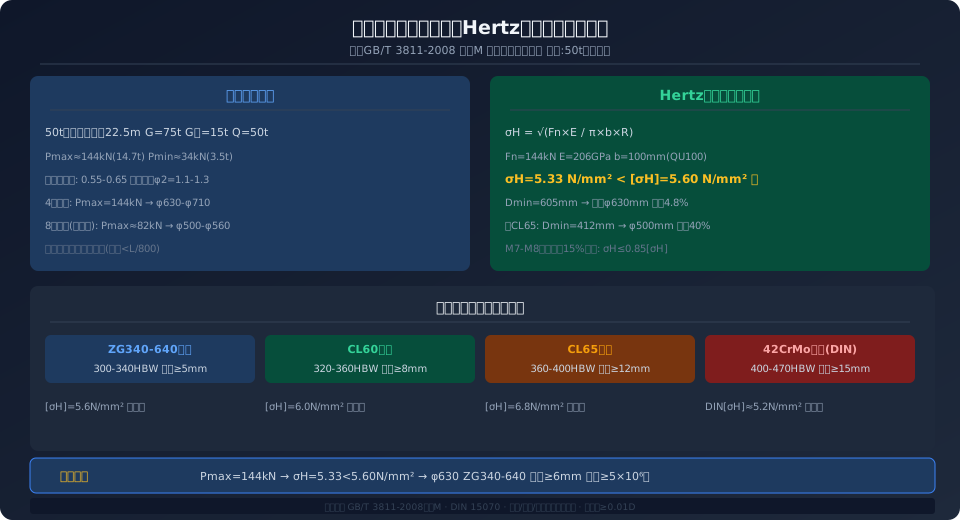
Crane Wheel Diameter & Wheel Load Check Guide
Crane wheel selection must balance three key parameters: maximum wheel load (Pmax ≤ allowable wheel load), wheel diameter (D ≥ Pmax × 3.06L / (σadm × b), where b is the effective contact width for a cylindrical tread), and tread material (ZG340-640 cast steel or CL60/CL65 forged steel, with tread hardness of 300–380 HBW and a hardened layer depth ≥ 5 mm). The design must also satisfy the Hertz contact stress limit of ≤ 1.5 × σadm (per ISO 4301, Annex M) and a fatigue life of at least 5 × 10⁶ operating cycles.
Crane wheels are the only load-bearing components in the travel mechanism that directly contact the crane rail. They carry the full vertical load of both the crane's dead weight and the lifted load, rolling across the rail tens of thousands of times per day. As a result, they are among the fastest-wearing and most frequently replaced wear parts in any lifting appliance. Per ISO 4301 (Crane Design Standard), Annex M, wheel diameter and tread width must be verified against the maximum wheel load using a strict Hertz contact stress check. Tread hardness and hardened layer depth must also be evaluated to ensure fatigue life meets the design standard.
In engineering practice, three common mistakes plague wheel selection:
① Increasing wheel diameter to handle higher loads — This rule-of-thumb approach ignores the matching constraints between rail model (QU70/QU80/QU100) and wheel tread width.
② Failing to distinguish driving wheels from driven wheels — Driving wheels typically wear 1.3 to 1.5 times faster than driven wheels (due to increased slip and skid during starting and braking) and should therefore be specified with one hardness grade higher.
③ Overlooking tread profile effects — Cylindrical and conical treads have significantly different impacts on wheel rail gnawing (flange rubbing) risk. Choosing the wrong profile can directly lead to skewed travel and abnormal wear.
Maximum Wheel Load Calculation and Distribution Analysis
The first step in wheel selection is accurately calculating the maximum wheel load for each wheel. For a double-girder bridge crane, the crane travel mechanism typically has 4 or 8 wheels (2 or 4 per end carriage). The maximum wheel load occurs when the loaded trolley travels to the extreme position at one end of the bridge — at that point, the combined force of the trolley dead weight plus the lifted load is concentrated on the set of wheels beneath the main girder rail on that side. Taking a 50t double-girder bridge crane (span L = 22.5 m, dead weight G = 75t, trolley dead weight Gtrolley = 15t, lifting capacity Q = 50t) as an example, and calculating per the wheel load distribution method in ISO 4301, Annex B.1: the maximum wheel load Pmax ≈ 144 kN (14.7t) and the minimum wheel load Pmin ≈ 34 kN (3.5t).
The accuracy of wheel load calculation directly affects all subsequent verification steps. Underestimating the wheel load leads to actual contact stresses exceeding allowable limits, causing premature pitting and spalling on the wheel tread. Overestimating it results in unnecessarily large wheel diameters, increasing overall crane height and manufacturing cost. Key factors influencing wheel load distribution are:
① Impact allowance — The impact factor during load hoisting is φ₂ = 1.1 to 1.3 (per ISO 4301, Table 3).
② Eccentric load coefficient — When the trolley is at its extreme position, the wheel load imbalance coefficient for the crane bridge is typically 0.55 to 0.65, meaning one side's wheels carry 55% to 65% of the total wheel load.
③ Dynamic effects — During emergency braking of the crane bridge, inertial forces momentarily increase the leading wheels' load by approximately 15% to 20%, which must be accounted for in fatigue verification.
When an 8-wheel configuration is used (4 wheels per side), the four wheels beneath each end carriage share the load through an equalizing beam (also called an "equalizing bogie"). The equalizing beam redistributes the crane's total wheel load from 4 wheel positions to 8, reducing the maximum load per wheel to roughly 55%–60% of a 4-wheel configuration. This allows for smaller wheel diameters or lower-grade rail sections at the same wheel load, but adds structural complexity and manufacturing cost to the end carriage. In practice, cranes in the 50t–100t class typically use the 8-wheel configuration, while those below 50t use 4 wheels.
One important caveat: the equalizing beam is not a universal solution. Its load-sharing capability is limited by two conditions. First, the beam's own bending stiffness must be sufficient (deflection < L/800, where L is the distance between the beam's two pivot points); otherwise, the beam itself will elastically deform and load distribution will remain uneven. Second, the rail elevations under the wheels at both ends of the equalizing beam must match (height difference ≤ 1 mm); otherwise, the wheel on the "higher" side carries more load, diminishing the equalizing effect. In new plants with steel crane rails, these conditions are generally easy to meet. However, in retrofit projects in older facilities, long-term settlement of the concrete floor can cause rail elevation discrepancies — in such cases, even with equalizing beams in place, the actual wheel load at each wheel should be verified on-site using a wheel load gauge or hydraulic jacks with pressure gauges to confirm the equalization performs as designed.
Hertz Contact Stress Verification and Wheel Diameter Selection
The core verification equation for wheel diameter is the Hertz line contact stress formula. According to Appendix M of the ISO 4301 Crane Design Standard, the contact stress σH for a cylindrical tread wheel on a flat-top rail (e.g., QU type) is calculated as σH=(Fn×E/(π×b×R))0.5, where Fn is the normal wheel load (N), E is the equivalent Elastic Modulus (2.06×10⁵ MPa for steel-on-steel), b is the effective tread contact width (mm), and R is the wheel radius (mm). The allowable contact stress [σH] depends on the Wheel Tread hardness — ZG340-640 Cast Steel (300HBW) allows [σH]=5.6 N/mm², CL60 Forged Steel (320HBW) allows 6.0 N/mm², and CL65 Forged Steel (360HBW) allows 6.8 N/mm².
Using a practical example (Pmax=144 kN, QU100 rail with tread width b=100 mm, wheel material ZG340-640), the minimum wheel diameter is derived by substituting σH≤[σH]=5.6 N/mm² into the formula: Rmin≥144,000×2.06×10⁵/(π×100×5.6²×10⁶)=302 mm, giving a minimum diameter Dmin=605 mm, rounded up to the standard diameter of 630 mm. The actual contact stress is then verified: σH,actual=(144,000×2.06×10⁵/(π×100×315))0.5=5.33 N/mm² < 5.6 N/mm², meeting design requirements with a safety margin of approximately 4.8%. If CL65 Forged Steel ([σH]=6.8 N/mm²) were used instead, the minimum diameter could be reduced to Dmin=412 mm, allowing a standard diameter of 500 mm — a 21% reduction in Wheel Diameter and roughly 40% lower Dead Weight, though the procurement cost of forged steel wheels is approximately 2.5 to 3 times that of Cast Steel.
It is important to note that the Hertz contact stress verification above applies only to the "pre-run-in" condition of new wheels on new rails. In practice, after running-in and wear, a slight curved contact patch forms between the Wheel Tread and the rail head (rail head radius of curvature Rrail head approximately 300–500 mm), and the actual line contact transitions to a mixed "point + line" contact mode, which can increase local contact stress by 20%–30% over the formula value. Therefore, for travel mechanisms under heavy Duty Classification (M7~M8), engineering practice recommends adding an additional 15% safety margin on top of the Hertz stress check — i.e., requiring σH,actual ≤ 0.85×[σH].
Tread Material and Hardening Process
The Hardness and depth of the hardened layer on the Wheel Tread directly determine its resistance to pitting and Wear. Common wheel materials fall into three grades:
①ZG340-640 Cast Steel — quenched and tempered with flame-hardened tread, Hardness 300–340HBW, hardened layer depth ≥5 mm, economical option suitable for M3~M5 duty travel mechanisms, priced at approximately ¥1,500–3,000 per wheel (φ630 Specification);
②CL60 Forged Steel — fully quenched and tempered with induction-hardened tread, Hardness 320–360HBW, hardened layer depth ≥8 mm, standard option suitable for M5~M6 duty, priced at approximately ¥3,500–6,000 per wheel;
③CL65 Forged Steel — fully quenched and tempered with deep induction-hardened tread, Hardness 360–400HBW, hardened layer depth ≥12 mm, heavy-duty option suitable for M7~M8 duty and High-Temperature Environment applications such as metallurgical Casting, priced at approximately ¥6,000–10,000 per wheel.
The engineering significance of tread hardening depth becomes clear when considering wheel operation: after approximately 2×10⁵ load cycles, surface micro-cracks (0.5–1.5 mm deep) begin to appear on the tread. If the hardened layer is only 3–4 mm deep, these micro-cracks can penetrate through it into the softer core material after roughly 5×10⁵ cycles—leading to large-scale spalling (the classic "fatigue spalling" failure mode). For wheels designed to achieve a 5×10⁶-cycle fatigue life, the hardened layer depth should therefore be no less than the expected wear depth (approximately 3–4 mm) plus a safe crack-propagation margin (approximately 2 mm), totaling 6 mm. This is precisely why Appendix M of ISO 4301 Crane Design Standard emphasizes the empirical rule: "For wheels with a wheel load exceeding 100 kN, the hardened layer depth must not be less than 1% of the wheel diameter."
The choice of hardening process is equally critical to long-term reliability. Flame quenching—rapidly heating the tread surface with an oxy-acetylene flame followed by water quenching—offers the lowest cost (¥80–150 per wheel) but delivers relatively poor hardened-layer depth uniformity (variation of ±1.5 mm). It suits small-to-medium wheels under φ500 mm operating in light-duty applications (M3 to M4). Induction hardening—using medium-frequency induction heating with water-spray quenching—represents the mid-to-high-end standard: hardened-layer depth is precisely controllable (accuracy of ±0.5 mm), and tread hardness uniformity is excellent (±15 HBW). This process is ideal for medium-to-large wheels above φ500 mm in applications rated M5 to M6. For heavy-duty wheels in the M7 to M8 class—such as those used on metallurgical cranes—a combined process of through hardening, tempering, and deep induction hardening of the tread surface is recommended. This yields uniform core toughness (preventing brittle fracture) while creating a 12–15 mm deep hardness gradient on the tread, ensuring a 5×10⁶-cycle fatigue life even under the most demanding operating conditions. Imported wheel brands (e.g., Demag, Konecranes) typically use Cr-Mo alloy steels such as 42CrMo4 with deep induction hardening, achieving tread hardness of 42–48 HRC (equivalent to 400–470 HBW) and hardened-layer depths of 15 mm or more—at a procurement cost roughly 3–4 times that of domestically produced CL60 wheels.
Frequently Asked Questions
Q: For a 50t double-girder bridge crane, should the crane bridge wheels be φ630 or φ710? When is a diameter upgrade necessary?
A: For a 50t double-girder overhead crane with a 22.5m span and a 4-wheel configuration, the Hertz contact stress on φ630 ZG340-640 cast steel wheels is approximately 5.33 N/mm², which meets the 5.60 N/mm² allowable limit per ISO 4301 (with a margin of only 4.8%). This configuration is acceptable. However, upgrading to φ710 is recommended in the following four scenarios: ① Work duty classification of M6 or higher (frequent start-stop cycles accelerate tread wear); ② Poor rail joint conditions (elevation differences >1mm amplify impact wheel loads to 1.5–2 times static values); ③ Dusty environments with abrasive particles that accelerate tread wear; ④ Expected operating cycles exceeding 3×10⁶ within 5 years. Upgrading to φ710 reduces contact stress to 4.2 N/mm², increasing the margin to 25%, at an additional cost of approximately ¥2,000–3,000 per wheel.
Q: Should wheel treads be cylindrical or tapered? In which applications is a tapered tread mandatory?
A: Cylindrical (flat) treads are suitable for most overhead and gantry cranes—they are simpler to manufacture, have well-defined contact stress calculations, and are easier to replace. Tapered treads (taper ratio 1:10 to 1:16) are primarily used in the following applications: ① Single-girder trolley hoist wheels (the tapered profile provides self-aligning to prevent skewing); ② Large-span gantry cranes with rail gauge >20m (the taper compensates for main girder deflection effects on wheel-to-rail contact angles); ③ Cranes operating on circular rails (the taper accommodates the wheel diameter differential between inner and outer curves). The drawback of tapered treads is that on straight rails they generate a continuous "creep force" toward the cone apex, accelerating wheel flange wear. This must be counterbalanced by adjusting the wheel block mounting angle or using flanged tapered treads. For standard overhead crane bridge travel mechanisms, cylindrical treads are the more reliable choice.
Q: How much tread hardening wear is too much before a wheel must be replaced? How can I quickly assess remaining service life?
A: Three criteria determine wheel replacement per ISO 4301, Appendix M.3: ① When the remaining hardened layer depth falls below 2mm (for wheels originally hardened to ≥5mm), hardness at 2mm below the tread surface drops below 200HBW, sharply increasing the risk of pitting and spalling; ② When tread diameter wear exceeds 3% of the original diameter (e.g., >19mm on a φ630 wheel), causing a diameter differential of more than 5mm between wheels on opposite sides of the crane bridge, which leads to wheel rail gnawing; ③ When spalling pits deeper than 3mm or through-thickness cracks appear on the tread surface. Quick field assessment: take three hardness readings with a portable hardness tester on the tread surface and average them—if hardness is below 250HBW and a visible network of fatigue cracks ("crazing") is present, schedule replacement immediately.
Q: What are the key differences between European (DIN) and Chinese (GB) crane wheel selection criteria?
A: The core differences between DIN 15070 and ISO 4301 in wheel selection are: ① DIN adopts a more conservative allowable contact stress—for the same material and hardness, DIN's [σH] is approximately 85%–90% of the GB value (e.g., for CL60, DIN's [σH] ≈ 5.2 N/mm² vs. GB's 6.0 N/mm²); ② DIN explicitly requires a hardened layer depth of ≥0.025×D (2.5% of wheel diameter, more stringent than GB's 1%), meaning a φ630 wheel requires a hardened layer of at least 16mm rather than 6mm; ③ DIN specifies a rigid matching table between minimum wheel tread width and rail profile (wheel tread width ≥ rail head width + 10mm), whereas GB allows greater flexibility. Consequently, overhead cranes designed to DIN standards typically require wheel diameters 1–2 sizes larger than their GB counterparts for the same capacity—for example, a 50t overhead crane would need φ710–800 wheels per DIN, while φ630–710 would suffice per GB.
Kelude Heavy Industry specializes in the design and manufacture of European-standard premium cranes, with a product range covering 50t–300t European Standard Double-Girder cranes, bridge cranes, and gantry cranes. We strictly adhere to ISO 4301 Crane Design Standard and the FEM/DIN international standard system, providing full-lifecycle technical services from solution design and product selection through installation and commissioning.
For travel mechanism selection calculation reports or technical solutions, contact the Kelude Heavy Industry engineering team: 13903802779.