

50t Double-Girder Crane Power Supply
📋 Key Summary
In high-frequency operational environments, the stability of a flexible combined power supply system is critical for the efficiency of a 50-ton Double-Girder Bridge Crane. This article analyzes the selection logic and installation specifications for such systems in European-standard double-girder cranes. By comparing the current-carrying capacity and voltage drop of cables with different cross-sections, we define the application scenarios for 16mm² and 25mm² copper-core cables across a 30m span. Furthermore, detailed guidelines on rail flatness and joint treatment are provided to ensure reliable on-site construction.
When designing the power supply system, it is essential to strictly adhere to the electrical load calculation and voltage drop regulations outlined in the FEM 1.001 Crane Design Specification. Additionally, on-site installation and acceptance must comply with the safety distance and insulation performance requirements for conductor rails and cable laying specified in the TSG 51-2023 Crane Safety Technical Supervision Regulation, ensuring inherent safety during equipment operation. As a manufacturer specializing in high-end customization of European-standard double-girder cranes ranging from 50t to 300t, Kelude Heavy Industry always prioritizes the reliability of the electrical system.
Selection Logic & Current-Carrying Capacity Verification for Cable Cross-Sections
Proper selection of cable cross-sections is fundamental to ensuring stable operation of the power supply system for a 50-ton Double Girder Crane. The selection process must not only meet the rated operational current requirements but also comprehensively account for the combined effects of voltage drop, ambient temperature, and laying methods on current-carrying capacity. In European Standard Double-Girder crane design, the response speed of the electrical system is crucial, particularly when the equipment incorporates an anti-sway algorithm; the voltage stability of the power supply directly impacts the precision of control signals.
Step 1: Calculate Total Installed Power. For a 50-ton double-girder crane, the Hoisting Motor power is typically 75kW. The Crane Travel Mechanism is equipped with two 15kW motors, and the Trolley Travel Mechanism uses a 7.5kW motor, resulting in a total installed power of approximately 112.5kW. Considering that mechanisms do not operate at full load simultaneously, a demand coefficient between 0.7 and 0.8 is applied, yielding a calculated power of approximately 80kW to 90kW.
Step 2: Calculate Rated Operational Current. Based on the three-phase AC power formula, with a line voltage of 380V and a power factor of 0.85, the system's rated current I = P / (√3 × U × cosΦ) = 90,000 / (1.732 × 380 × 0.85) ≈ 161A. If calculated based on full load of 112.5kW, the peak current can reach 201A.
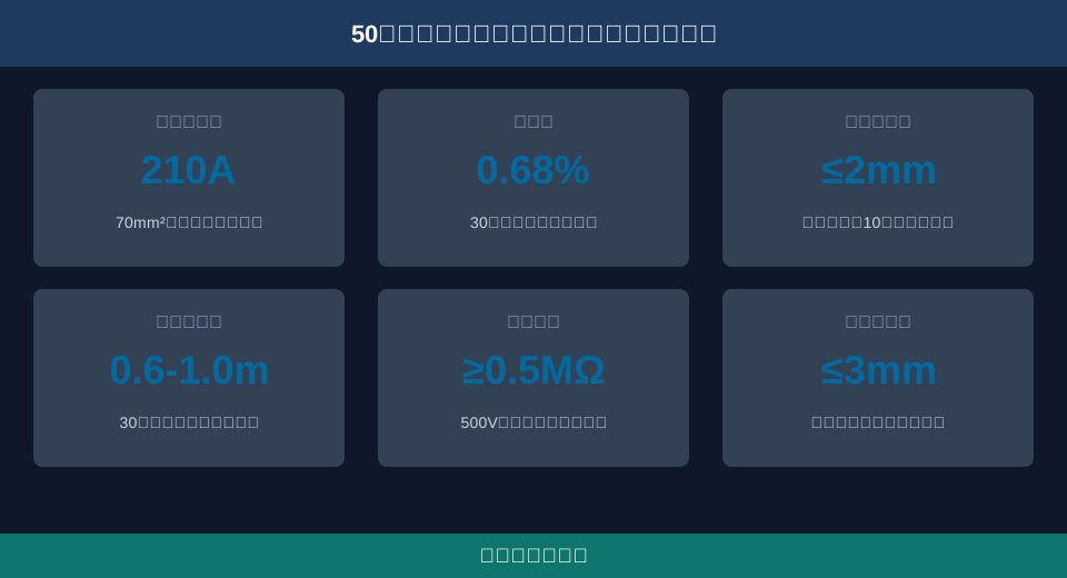
Step 3: Verify Cable Current-Carrying Capacity and Voltage Drop. Taking a 30m power supply span as an example, let us verify the voltage drop using a 70mm² copper-core cable. A 50mm² copper-core cable has a current-carrying capacity of approximately 170A at an ambient temperature of 40°C, while a 70mm² cable has a capacity of approximately 210A, which meets the peak demand of 201A.
Engineering Calculation: Calculating the voltage drop for a 70mm² copper-core cable over a 30m span. Given the resistivity of copper ρ=0.0175 Ω·mm²/m, cable length L=30m, and cross-section S=70mm². Single-phase resistance R = ρ × L / S = 0.0175 × 30 / 70 = 0.0075 Ω. At a peak current I=201A, the line voltage drop ΔU = √3 × I × R = 1.732 × 201 × 0.0075 ≈ 2.61V. The voltage drop percentage = 2.61 / 380 × 100% ≈ 0.68%, which is well below the 3% limit required by specifications, confirming the selection is appropriate.
Flatness Control for Flexible Combined Power Supply Rail Installation
The installation quality of the pulley block rail directly determines the smoothness of flexible cable deployment and its service life. Deformation or misalignment at rail joints can cause the pulley block to jam, accelerating wear on the cable sheath. Before rail installation, the main girder structure should be assessed; if necessary, weld crack detection should be performed to ensure that welding and fixing of rail supports do not compromise the strength of the main girder base metal.
First, laser level calibration should be used for the positioning and welding of rail supports to ensure the entire rail lies on the same horizontal plane. Support spacing is typically set between 1.5m and 2.0m to guarantee rail rigidity. After welding, anti-corrosion treatment must be applied to the weld seams, coating them with zinc-rich primer and topcoat, with a total coating thickness of no less than 120 microns.
Second, the misalignment at rail joints must not exceed 0.5mm to prevent severe vibration when the pulley block passes through. The joint gap should be controlled between 2mm and 4mm, secured using specialized connection plates and high-strength bolts. The tightening torque for M12 bolts must reach 45N·m to ensure the joint does not loosen under long-term vibration.
Finally, a no-load test run should be conducted after installation to observe the pulley block's performance at a speed of 120m/min. The straightness deviation of the rail must be strictly controlled to no more than 2mm per 10m. If any jamming or abnormal noise is detected, the machine must be stopped immediately for adjustment to ensure smooth operation without obstruction.
Cable Sag and Tension Adjustment Technology for Crane Travel Mechanism
Adjusting cable sag is a core technical challenge in flexible power supply systems. Excessive sag can lead to cable dragging and wear, while insufficient sag may cause internal wire fracture due to thermal contraction or load stretching. In our European-standard double-girder crane designs, Kelude Heavy Industry introduces modular tension adjustment components for the crane travel power supply system, significantly improving on-site commissioning efficiency and system reliability.
First, set the initial sag based on ambient temperature. At a normal temperature of 20°C, the cable sag for a 30m span should be adjusted to between 1/50 and 1/30 of the span, i.e., 0.6m to 1.0m. Sag measurement should be taken with the cable stationary, measuring the vertical distance from the lowest point of the cable to the lower edge of the rail.
Second, configure appropriate counterweight blocks. Typically, 15kg cast iron counterweight blocks are used to maintain constant cable tension via gravity. The counterweight block must be installed at the end of the cable guide and ensure its trajectory is not interfered with by surrounding structural components. The weight of the counterweight block requires precise calculation based on the cable's unit length weight and the friction force of the pulley block.
Third, add windproof guy wires. In coastal areas or regions with strong winds, the breaking force of the windproof guy wire must exceed 5000N to prevent the cable from being torn off by strong gusts. The guy wire should use galvanized wire rope and be equipped with turnbuckles for tension adjustment, ensuring the cable maintains a safe posture even in extreme weather conditions.
Routine Maintenance & Insulation Performance Testing for 50t Overhead Crane Power Systems
Long-term stable operation of the power supply system depends on standardized routine maintenance. Insulation Resistance is a core indicator, directly impacting operator safety and equipment reliability. During inspection and repair, strict adherence to anti-collision safety distance regulations is mandatory to ensure adequate safety distance between maintenance personnel and active machinery.
Monthly checks require measuring phase-to-phase and phase-to-ground Insulation Resistance of cables using a Megohmmeter (Insulation Tester) rated at 500V. Values must not fall below 0.5MΩ. Before measurement, disconnect the Power Supply and Dismantle cables from the Electrical Cabinet and Pulley block Terminal Blocks to prevent interference from other electrical components. If readings are low, troubleshoot for damaged or damp cable sheathing.
Quarterly inspections should assess Crane wheel wear on pulley blocks. Replace immediately if Wheel Diameter wear exceeds 3 mm or if severe out-of-roundness occurs. Check for smooth rotation in bearings; clean internal grease and dust, then reapply lithium grease to extend service life.
Prior to the rainy season annually, Tighten Conductor Rail Terminal Blocks to prevent poor contact caused by thermal expansion and contraction. Clean Crane Rail surfaces of oil and dust to prevent pulley slippage. Kelude Heavy Industry recommends maintaining comprehensive equipment maintenance logs to track data, identify potential issues early, and achieve Preventive Maintenance.
During each Overhaul, conduct a thorough examination of insulator surface condition on the busbar. Replace or clean insulators showing Crack formation or contamination exceeding the characteristic value. For high-current operating conditions (e.g., continuous rated load), perform infrared temperature rise detection on cable joints every six months. Temperature rise must not exceed 60℃ to ensure electrical reliability at connection points.
| Cable Cross-SectionAccumulation (mm²) | Ratedcurrent-carrying capacity (A) | 30MetersFull loadVoltage drop (%) | Application Scenariosrecommendation |
|---|---|---|---|
| 35 | 135 | 2.1 | Light load/ShortSpanoperating condition |
| 50 | 170 | 1.5 | Standard50tDouble Girder Crane |
| 70 | 210 | 1.0 | Heavy load/High-frequency Operationenvironment |
| 95 | 260 | 0.8 | Overlarge span/High-Temperature Environment |
Frequently Asked Questions
Q: How to prevent the flexible power cable of a 50-ton double-girder crane from breaking in low-temperature environments?
A: Low temperatures cause the cable jacket to harden and reduce flexibility. Kelude Heavy Industry recommends increasing the initial sag by 10% to 15% during winter to allow for thermal expansion and contraction. Additionally, use special rubber-sheathed cables rated for low-temperature service, with a lower operating limit of -40°C (-40°F), ensuring excellent bending performance even in severe cold.
Q: How to troubleshoot jamming issues after pulley block rail installation?
A: Jamming is usually caused by rail deformation or misalignment at joints. First, check the rail straightness, ensuring the deviation does not exceed 2 mm per 10 meters (approx. 32.8 ft). Second, use a feeler gauge to measure the misalignment at joints; if it exceeds 0.5 mm, re-grind or adjust the supports. Finally, inspect the wheel bearing for lack of grease or damage, adding grease or replacing the bearing as necessary.
Q: What are the advantages of a flexible power supply system compared to a conductor rail power supply system?
A: The flexible combined power supply system uses trailing cables, offering better toughness and vibration resistance, making it ideal for operating conditions with high travel speeds and frequent deceleration. Unlike rigid conductor rails, it eliminates carbon brush wear and sparking issues, provides superior insulation, and has lower installation and maintenance costs, effectively reducing the failure rate of electrical faults.
Q: How to determine if the power supply cable needs complete replacement?
A: Complete replacement is required when the cable exhibits the following conditions: first, deep cracks on the jacket exposing the internal shielding layer; second, Insulation Resistance Test values consistently below 0.5 MΩ that cannot be restored through local repair; third, strand breakage in the internal cores causing severe three-phase current imbalance. Periodic inspection is a key method to avoid unexpected downtime.
