

Crane Drum Wear Detection & Groove Repair Standards
📋 Key Summary
The crane drum, a critical load-bearing component of the hoisting mechanism, directly dictates wire rope service life and operational safety through its rope groove wear levels. Standard protocols mandate immediate repair or replacement when wall thickness wear reaches 15% of the original design or groove depth loss exceeds 2 mm (0.08 in). For European Standard Double-Girder cranes rated between 55 tons and 330 tons, implementing regular Non-destructive testing and groove turning repairs can reduce equipment failure rates by over 30%, ensuring uninterrupted Continuous operation under heavy loads.
In the maintenance framework for lifting appliances, drum health assessment must strictly adhere to FEM 1.001 Crane Design Specification. Additionally, compliance with routine inspection and periodic inspection requirements is governed by the TSG 51-2023 Safety Technical Supervision Regulation. When providing high-end customization for 55-ton to 330-ton European standard double-girder cranes, Kelude Heavy Industry prioritizes full life cycle management of the drum assembly as a core technical service pillar, ensuring every delivered unit possesses a robust mechanical foundation.
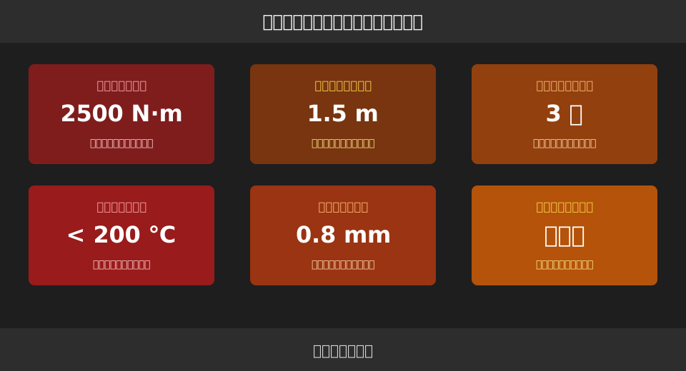
Quantified Inspection Standards for Drum Wall Thickness and Groove Wear
The uniformity of drum wall thickness and the geometric precision of rope grooves are fundamental indicators for assessing the safety status of the hoisting mechanism. During practical inspections, technicians utilize specialized measuring tools to obtain precise data, determining whether the drum remains fit for continued service.
First, for measuring drum wall thickness, an ultrasonic thickness gauge with 0.1 mm (0.004 in) accuracy is required. Measurement sections should be selected every 300 mm (11.8 in) along the developed length of the drum, with four evenly distributed measurement points per section. If the wear amount at any point reaches 15% of the original design thickness, the drum is deemed to have reached its scrap limit. For 55-ton cranes, where drum wall thickness typically ranges from 20 mm to 25 mm (0.79–0.98 in), the wear limit must be precisely controlled within 3 mm to 3.75 mm (0.12–0.15 in).
Second, for evaluating groove depth wear, technicians use vernier calipers or depth gauges to measure the distance from the bottom of the rope groove to the outer diameter of the drum. If the rope groove radius wear exceeds 2 mm (0.08 in), or if distinct stepped wear appears at the groove bottom, a re-evaluation of the wire rope winding state is mandatory. Taking a 20 mm (0.79 in) wire rope as an example, the characteristic value for the rope groove radius should be 10.5 mm (0.41 in). If the worn radius falls below 8.5 mm (0.33 in), the contact area with the wire rope decreases, accelerating wire breakage and strand failure.
Kelude’s technical team recommends simultaneously recording corrosion pit depths on the drum surface during inspection. If corrosion pit depth exceeds 5% of the wall thickness, a comprehensive safety assessment incorporating the stress concentration factor is required, even if the overall wall thickness remains within limits, necessitating early repair arrangements if necessary.
Turning Repair Process Parameters for Heavy-Duty Double-Girder Crane Drums
When groove wear exceeds standards but the overall drum wall thickness still meets strength requirements, turning repair is an effective method to restore geometric precision. The repair of drums for heavy-duty double-girder cranes imposes strict requirements on machine tool rigidity, tool selection, and cutting parameter settings.
First, before turning repair, the drum must undergo comprehensive dynamic balancing verification. For heavy-duty double-girder cranes with a Lifting Capacity exceeding 110 tons, the residual unbalance of the drum must be controlled within G6.3 level. This requires strict calculation of the permissible unbalance mass-radius product based on specific Rotational speed to prevent severe vibration during machining.
Second, tool selection and feed rate settings directly impact repair quality. In the roughing stage, the feed rate can be set to 0.5 mm/r (0.02 in/rev) to quickly remove the fatigue layer; in the finishing stage, the feed rate must be reduced to 0.3 mm/r (0.012 in/rev), accompanied by ample cutting fluid for Cooling. In the Kelude workshop, the surface Roughness of the finished rope groove must meet Ra3.2 standards, and the groove pitch error must not exceed ±0.2 mm (±0.008 in) to ensure neat wire rope arrangement on the drum and avoid rope biting.
Under conditions where the drum outer diameter D is 800 mm (31.5 in) and the initial spindle speed n is set to 15 r/min, the cutting speed v can be calculated using the formula v = π × D × n / 1000. Substituting the values yields a theoretical cutting speed v = 3.1416 × 800 × 15 / 1000 ≈ 37.7 m/min. However, to achieve the Ra3.2 surface Roughness requirement and match the cutting range of cemented carbide tools, the target cutting speed needs to be increased to 45 m/min. At this point, the spindle speed must be recalculated: n = 1000 × v / (π × D) = 1000 × 45 / (3.1416 × 800) ≈ 17.9 r/min. Through this precise calculation, workshop operators can accurately adjust the machine speed to 18 r/min, thereby ensuring the machining quality of the rope groove surface.
Fatigue Crack Detection at Drum Flange and Bearing Housing Connections
The connection area between the drum flange and the bearing housing is a high-risk zone for stress concentration, prone to initiating fatigue cracks under long-term alternating load exposure. Detecting such hidden defects requires deep diagnosis using Non-destructive testing technologies.
The connection area between the drum flange and the bearing housing is a high-risk zone for stress concentration. When inspecting for fatigue cracks in these areas, one can refer to the non-destructive testing logic used in weld crack detection for main girders, employing Magnetic Particle Inspection (MPI) or penetrant testing for surface defect recognition. The sensitivity of MPI must be capable of identifying minute surface cracks longer than 2 mm (0.08 in) and narrower than 0.1 mm (0.004 in).
First, for the circumferential weld seam connecting the drum flange to the barrel, special attention must be paid to the weld toe for microscopic cracks. During the hoisting and Braking processes of the crane, this area can endure alternating stress cycles exceeding 10^6 times. If a crack depth exceeds 0.5 mm (0.02 in) or the crack length exceeds 10% of the total weld length, it is deemed non-compliant, requiring grinding removal or welding repair.
Second, wear and deformation of the bearing housing mounting holes also require quantified detection. Using a dial indicator to measure the roundness and cylindricity of the bearing housing bore, the tolerance value should be controlled within IT7 level. When the bearing housing bore becomes elliptical by more than 0.05 mm (0.002 in) due to long-term compression, uneven stress distribution on the Outer Ring occurs, accelerating Bearing Failure. During Factory Acceptance Test, Kelude exercises strict control over geometrical tolerances at this location to ensure structural Stability during long-term heavy-load operation.
Preventive Maintenance Cycle Planning for Hoisting Mechanism Drums in European Standard Cranes
Combined with the optimization of hoisting smoothness via anti-sway control algorithms, mechanical maintenance of the drum also requires refined cycle management. Scientific Preventive Maintenance effectively extends the service life of drums and bearings, reducing unplanned downtime.
First, lubrication maintenance of the drum bearing is the core of preventive management. For continuous operation heavy-duty cranes, it is recommended to replace bearing Grease every 2,500 operating hours or every six months. Taking a standard double-row spherical roller bearing as an example, the fill quantity for each application should be controlled between 30% and 50% of the internal free space, with a single fill quantity of approximately 1.5 kg (3.3 lbs). Overfilling causes elevated bearing operating temperatures, while underfilling leads to dry friction.
Second, monitoring operating temperature is a key Indicator for assessing the health of drum components. After two hours of Continuous operation under rated load, the temperature rise limit of the outer ring should be controlled within 40 K, and the absolute operating temperature must not exceed 75°C (167°F). If the thermometer indicates abnormal temperature rise, immediate shutdown inspection of the lubrication status or Bearing Clearance is required. European standard equipment delivered by Kelude reserves installation interfaces for Temperature Sensors, facilitating user integration into the condition monitoring system for dynamic adjustment of maintenance cycles.
| test items | scrappingrelated to repairthreshold | repair processandrequirements | inspection toolfrequency of |
|---|---|---|---|
| drum wall thickness | Wearto original thickness 15% | overallscrapping,not allowedbuild-up welding repair | ultrasonic thickness gauge,semi-annually 1 times |
| rope groovedepth | radiusWearexceeding 2mm | turning repair,surface roughness Ra3.2 | depth gauge/caliper,quarterly 1 times |
| flange ringWeld Seam | Crackdepth exceeds 0.5mm | ground out oraccording to the standardweld repair | Magnetic Particle Inspection (MPI)gauge,annually 1 times |
| Bearing Housinghole | ovality greater than 0.05mm | Boringrepair orreplacementBearing Housing | inner diameterdial indicator,annually 1 times |
FAQ
Q: At what point must a drum be replaced instead of repaired?
A: Replacement is mandatory when the drum wall thickness wear reaches 15% of the original design thickness, or if severe step-like wear appears at the rope groove bottom with a wear amount exceeding 2 mm. If turning repair cannot restore sufficient strength, the entire unit must be replaced. For high-strength heavy load applications, direct replacement is recommended to ensure safety.
Q: How do you ensure surface roughness meets standards during rope groove repair?
A: During the finishing turn phase, feed rate must be controlled within 0.3 mm/r using sharp carbide cutting tools. Continuous and adequate coolant flow is essential to reduce cutting zone temperature. Post-machining, spot checks with a roughness tester are required to ensure the rope groove surface Roughness meets the Ra3.2 standard.
Q: Can minor cracks at the junction between the drum flange and shell be welded?
A: If crack depth is less than 0.5 mm and length is short, they can be ground out completely followed by penetrant testing to confirm no residual defects. For deeper cracks, qualified welders must use matching welding consumables for repair. Post-weld Annealing is mandatory to relieve stress, followed by non-destructive testing.
Q: Can Preventive Maintenance fully replace regular non-destructive testing?
A: No. Preventive maintenance focuses on Lubrication, Tightening, and Visual inspection, while non-destructive testing is critical for detecting internal and microscopic surface Defects. Both methods should be used together; routine maintenance records provide data support for dynamically adjusting flaw detection cycles.
