

How to Choose Crane Encoders: Incremental vs Absolute Multi-Turn
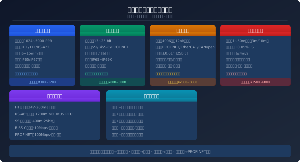
Crane encoders are the core sensors for position feedback and speed closed-loop control. They are classified by operating principle into incremental types (resolution 1024–5000 PPR) and absolute types (single-turn 13–25 bit / multi-turn 4096 revolutions), with interface protocols covering HTL/TTL push-pull, RS-485, SSI, BiSS-C, PROFINET, and more. Selection should be based on positioning accuracy requirements, mechanical mounting space, and environmental protection rating.
Encoders are indispensable position feedback components in crane electrical control systems. Whether it's bridge crane bridge travel positioning, trolley traverse control, hoisting height detection, or gantry crane rigid outrigger synchronization correction, encoders provide the precise position and speed signals required. As crane intelligence continues to advance, encoder selection has evolved from a simple "as long as it outputs pulses" approach to a comprehensive evaluation covering resolution accuracy, interface protocol compatibility, mechanical mounting method, environmental protection rating, and total lifecycle cost.
This article references ISO 4301 (Crane Design Standard) and IEC 60204-32 (Electrical Safety of Machinery), along with the positioning accuracy requirements of FEM 1.001 for general purpose bridge cranes, to systematically outline the selection criteria, installation specifications, and common fault diagnosis for four encoder types: incremental, absolute single-turn, absolute multi-turn, and draw-wire.
Encoder Types and Operating Principles
Crane encoders fall into four categories based on operating principle and output signal type, each suited to specific applications:
Incremental encoders — Output three square-wave pulse signals: A, B, and Z. The 90° phase shift between A and B determines rotation direction, while the Z channel provides one pulse per revolution as a zero reference. Standard resolutions are 1024 PPR, 2048 PPR, 3600 PPR, and 5000 PPR. Key advantages include fast response (output frequency up to 300 kHz) and low cost (¥300–1200). The main drawback is the lack of absolute position memory — after a power loss or PLC restart, a "homing" routine must return to the reference point. Ideal for speed closed-loop feedback on hoisting, bridge travel, and trolley drives, as well as simple positioning applications that don't require power-loss memory.
Absolute single-turn encoders — Each angular position corresponds to a unique digital code (e.g., 13-bit = 8192 points/revolution, 25-bit = 33,554,432 points/revolution), output in real time via SSI synchronous serial interface or BiSS-C bidirectional interface. Position is read immediately upon power-up with no homing required. With protection ratings up to IP67–IP69K, these suit drum rotation angle detection and slewing mechanism positioning where single-turn absolute position is required. Typical price: ¥800–3000.
Absolute multi-turn encoders — Add a mechanical gearbox to the single-turn absolute design to record absolute position over 0–4096 revolutions (e.g., 12-bit gear + 13-bit single-turn = 25-bit combined resolution). Multi-turn counting requires no battery (using Wiegand effect or gear ratio memory), so revolution count is retained after power loss. Supports PROFINET, EtherCAT, CANopen, and other industrial Ethernet interfaces, transmitting position, speed, temperature, and diagnostic data simultaneously. Suitable for full-range hoisting height detection, multi-crane synchronization control, and anti-sway systems requiring absolute coordinates across the entire travel range. Typical price: ¥2000–8000.
Draw-wire encoders — Convert linear displacement into encoder rotary motion via a stainless steel wire and spring return mechanism. Built-in absolute multi-turn encoder with measuring ranges of 1–50 m (3 m, 5 m, and 10 m are common for lifting height), linearity of ±0.05% F.S., and maximum wire speed of 4 m/s. Installation is straightforward — the encoder body mounts to the bridge frame while the wire tip attaches to the moving component (trolley or hook block), eliminating the need for couplings and brackets. Well suited for bridge travel distance detection, trolley traverse position feedback, and auxiliary lifting height measurement. Typical price: ¥1500–6000.
Key Technical Parameters
Encoder Selection Comparison by Application
The table below provides a side-by-side comparison of core selection parameters across the four encoder types for typical crane applications. When selecting, prioritize three key constraints: positioning accuracy requirements, PLC interface type, and available mounting space.
| Comparison Parameter | Incremental | Absolute Single-Turn | Absolute Multi-turn | Draw-Wire |
|---|---|---|---|---|
| Positioning Accuracy | Depends on Multiplier Circuit 4After Multiplication Reaches0.018° | 13bit≈0.044° 25bit≈0.00002° | Same as Single-Turn+12bit Turns Full Measuring Range Absolute Position | ±0.05%F.S. 1mMeasuring Range±0.5mm |
| Power-Off Memory | None Homing Required on Power-Up | Yes(Absolute Single-Turn) Immediate Recovery Angle | Yes(Full Measuring Range) No Homing Required | Yes Built-in Absolute encoder |
| Common Interfaces | HTL (high-threshold logic)(24VPush-pull) TTL (transistor-transistor logic)(5V)/RS-422 | SSI (Synchronous Serial Interface)(Synchronization Serial) Bi SS (Bidirectional Synchronous Serial)-C(Bidirectional) | PROFINET/Ether CAT CANopen/Device Net | Same as Built-in Encoder Analog4~20mAOptional |
| Mounting Type | Solid Shaft+Coupling Clamping Flange/Servo Clamping Flange | Solid Shaft/Blind Bore/Through Bore Torque Arm Fixing | Same as Single-Turn Increase Gearbox Size | Encoder Fixing+Draw Wire Wire End Attached to Moving Part |
| Protection Rating (IP) | IP65(Standard) IP67(Heavy-Duty) | IP65~IP67 IP69K(Sanitary) | IP65~IP67 | IP65(Wire Exit) IP54(Economy) |
| Application Scenarios | Motorspeed closed loop Simple Positioning(Homing Required on Power-Up) | Drum Angle Detection Slewing mechanism Positioning | Lifting Height Full Range Detection Anti-sway Synchronization·Multi-Crane Coordination | Crane Bridge / Long Travel/Trolley Travel Distance Measurement Lifting Height Auxiliary |
| Reference Price | ¥300~1200 | ¥800~3000 | ¥2000~8000 | ¥1500~6000 |
Encoder Installation Standards and Wiring Requirements
Installation quality directly determines encoder measurement accuracy and service life. IEC 60204-32 specifies clear requirements for routing encoder signal cables:
Mechanical Installation — The coaxiality deviation between the encoder shaft and the motor shaft or drum shaft must be kept within ±0.05 mm (may be relaxed to ±0.2 mm when a flexible coupling is used). Use stainless steel bellows-type or jaw-type flexible couplings; rigid connections are not permitted. The mounting bracket must have sufficient stiffness — a thick steel plate of at least 6 mm, bent to shape, is recommended. Vibration acceleration at the mounting point should be kept below 5 g. For hollow-shaft encoders, ensure the axial clamping force does not exceed the manufacturer's specified maximum (typically 40–80 N).
Electrical Wiring — Encoder signal cables must be routed separately from power cables, with a minimum separation of 200 mm. Where crossing is unavoidable, the crossing angle must be 90°. The shield must be grounded at both ends (encoder side and PLC side) using EMC cable clamps, with a grounding wire cross-section of at least 4 mm². HTL push-pull output signals can be transmitted up to 200 m (with 0.75 mm² cable); RS-485 differential signals can reach 1,200 m. PROFINET interfaces require industrial Ethernet cable of CAT5e or better, with a maximum length of 100 m.
Protective Measures — Encoders mounted at the drum shaft end must be fitted with a protective cover to prevent wire rope lubricating oil from dripping onto the unit and to keep dust from accumulating. For operation in high-temperature environments (ambient temperature above 60°C), install a thermal barrier (3–5 mm ceramic fiber board) between the mounting bracket and the encoder; if necessary, add compressed-air purge cooling. For outdoor crane installations, place a desiccant pack inside the encoder junction box and use metal waterproof cable glands (IP68 rated) at all wiring entries.
Common Encoder Faults: Troubleshooting and Repair
Crane encoder failures typically present in one of three ways: complete signal loss (PLC reports "encoder fault"), signal jumping (position values fluctuate randomly), and zero-point drift (position resets or shifts after power loss). Below is a fault-by-fault breakdown of causes and troubleshooting steps:
Complete Signal Loss — First, check the supply voltage (HTL encoders typically operate at 10–30 VDC; TTL encoders at 5 VDC ±5%). Measure the voltage at the encoder terminals with a multimeter — it must not drop below 90% of the rated value. Next, verify cable continuity: probe the signal lines at the PLC end with an oscilloscope — a square-wave pulse train should be present under normal conditions. If no signal is detected, work backward through any intermediate junction boxes and drag chain cable sections. Common culprits include broken conductors inside the drag chain cable (fatigue from repeated flexing) and loose or oxidized terminal block connections.
Signal Jumping / Lost Pulses — The position value read by the PLC jumps randomly (e.g., from 12345 to 15678 and back). Three primary causes: ① Electromagnetic interference — when VFD output cables run parallel to encoder signal cables, high-frequency PWM noise couples into the signal lines. Install an output reactor (du/dt filter) at the frequency inverter output. ② Poor shield grounding — the shield is grounded at only one end, or the grounding resistance is too high (should be below 4 Ω). ③ Coupling slippage — an aging flexible coupling loses torque transmission capacity, causing angular slip during acceleration and deceleration. Replace the coupling and recalibrate.
Zero-Point Drift / Loss — An incremental encoder loses its zero reference after a power cycle. Troubleshooting steps: ① Confirm the PLC program saves the current count value to a retentive register before power-down. ② Check the Z-phase (zero) pulse — one pulse per revolution, approximately one-quarter of a period in width. ③ If an external proximity switch is used for the zero reference, verify the sensing distance is within the specified range (typically 2–4 mm). For an absolute encoder, a "revolution count reset" usually indicates a stuck internal gear mechanism or a failed Wiegand sensor module — the unit must be returned to the factory for repair.
| Fault Symptom | Possible Cause | Troubleshooting Method | Solution |
|---|---|---|---|
| Complete Signal Loss | Power Supply Anomaly Cable Broken Core Loose Terminal | multimeter Check Power Supply Voltage oscilloscope Inspect Signal Waveform Section-by-Section Wiring Check | Restore Power to Rated Value Replace Drag Chain Cable Section Tightening/Replace Terminal |
| Position Value Jump | Frequency Inverter / VFDElectromagnetic Interference Shield Grounding Poor Coupling Slipping | Shutdown Frequency Inverter / VFDObserve After Measure Grounding Resistance(Should<4Ω) Check Coupling Elasticity Body | Add Output Reactor Dual-End Grounding·Replace with Shielded Cable Replace Coupling |
| Zero Drift | PLCCounter Value Not Saved ZPhase Pulse Loss Proximity Switch / Inductive Sensor Distance Deviation | Check Power-Off Retentionregister oscilloscope Measure ZPhase Pulse Measure Sensing Distance | Enable Power-Off Retention Function Replace Encoder Air Compressor Mounting Distance |
| Temperature Alarm | Ambient Temperature Out of Range Internal Bearing Lack of Lubrication Poor Heat Dissipation | Infrared Temperature Measurement·Record Trend Acoustic Diagnosis Bearing Abnormal noise Check Ventilation Conditions | Install Heat Shield/Air Cooling Return to Factory for Replacement Bearing Improve Ventilation |
| Communication Interruption | PROFINETCable Break IPAddress Conflict network switch Port Fault | ping Testing Connectivity Check Network Topology Change Port Testing | Replace Industrial Ethernet Cable Reassign IP Replacenetwork switch |
| Wire Does Not Retract | Internal Spring Fatigue Wire Sticking/Corrosion Outlet Blockage | Manual Stretching Testing Inspect Wire Surface Clean Outlet | Replace Spring Mechanism Replace Stainless Steel Draw Wire Clean and Lubricate Dust Cover |
Calibration & Commissioning Procedures
Once the encoder is installed, follow these steps to commission and calibrate the system, ensuring position feedback accuracy meets the requirements of the crane control system:
Step 1: Static Check — Power up the encoder and monitor its live value in the PLC programming software. With the crane fully stationary (brakes applied, motor de-energized), observe the position value fluctuation. For an incremental encoder, fluctuation should be <±2 pulses (or <±8 counts after 4x quadrature multiplication); for an absolute encoder, fluctuation should be <±1 LSB. If fluctuation is excessive, check the encoder supply ripple (should be <50 mVpp) and grounding quality.
Step 2: Zero-Position Calibration — Incremental encoder: Move the crane to its physical zero position (e.g., bridge end limit switch, hoist lower limit), then run the PLC homing routine — move slowly toward the zero position and reset the counter when the Z-phase pulse rising edge is detected. Absolute encoder: Use the "preset value" function in the PLC — write the encoder reading corresponding to the current physical position into the preset register; all subsequent position values are calculated as offsets from this reference. The preset value is calculated as: Preset Value = Target Position (mm) × (Resolution / Travel per Revolution).
Step 3: Full-Travel Verification — Run the crane through its full travel at low speed (<10% of rated speed). At five points — start, 25%, 50%, 75%, and end — measure the actual physical position using a laser distance meter or tape measure, and compare against the encoder feedback value displayed on the PLC. Position deviation should be ≤±(0.1% of range + 1 encoder resolution). If deviation exceeds tolerance, check the transmission ratio setting between the encoder and the measured shaft, and inspect the coupling for angular slip.
Step 4: Dynamic Accuracy Test — Run the crane at 25%, 50%, and 100% of rated speed, recording the PLC position tracking error curve. During acceleration and deceleration, tracking error may temporarily increase to 3–5 times the static accuracy, but steady-state error (during constant-speed travel) must return to within static accuracy limits. For anti-sway control systems, dynamic position error should be ≤±5 mm (hoisting) and ≤±10 mm (bridge/trolley); otherwise, check whether the encoder update rate is sufficient (recommended ≥1 kHz).
Further Reading & Standards
• FEM 1.001-1 — General Purpose Bridge Crane Standard: electrical control system requirements for overhead crane design.
• GB/T 28264-2012 Safety Monitoring and Management System for Lifting Appliances: data acquisition and recording requirements for position sensors in safety monitoring systems.
Frequently Asked Questions
Q: For hoist lifting height detection, should I use an absolute multi-turn encoder or a draw-wire encoder? What's the difference?
A: For hoisting height detection, an absolute multi-turn encoder (mounted on the drum shaft) is the preferred choice. It calculates height by multiplying drum rotation count by rope travel per revolution, achieving accuracy of ±3–5 mm. A draw-wire encoder serves as an alternative solution, particularly for retrofit projects — the wire simply attaches to the hook block, making installation straightforward. However, the draw-wire assembly has a shorter service life in high-temperature and dusty environments (typically requiring replacement every 2–3 years). The cost difference between the two is roughly 3–5 times, with the multi-turn encoder being more expensive. For new installations, the multi-turn encoder is recommended, in line with ISO 4301 requirements for hoisting mechanism safety monitoring.
Q: What PPR rating is sufficient for an incremental encoder used for bridge crane long-travel distance measurement?
A: Long-travel positioning accuracy is typically required to be ±10 mm. Taking a wheel diameter of Φ400 mm and a reduction ratio of i=50 as an example: travel per wheel revolution = π × 400 ≈ 1256 mm; motor revolution corresponds to bridge travel of 1256/50 ≈ 25.1 mm. With a 2048 PPR encoder (8192 pulses per revolution after 4x quadrature), each pulse corresponds to 25.1/8192 ≈ 0.003 mm — far exceeding the accuracy requirement. In practice, 1024–2048 PPR is sufficient; higher PPR values provide no meaningful accuracy improvement and only add unnecessary load to the PLC high-speed counter module.
Q: The encoder signal keeps jumping and the PLC reports a position deviation fault. How do I quickly determine whether it's interference or a faulty encoder?
A: First, power down the VFD (open the input disconnect switch) and observe the encoder signal: ① If the signal returns to normal, the issue is confirmed as VFD PWM interference — install a sine filter or output reactor on the VFD output, and replace the encoder cable with a double-shielded twisted-pair cable (aluminum foil + tinned copper braid, dual-layer shielding). ② If the signal still jumps, use an oscilloscope to measure the A/B phase waveforms directly at the encoder end. If the waveform edges are jittery or the amplitude is attenuated, the encoder's internal circuitry is faulty and the unit needs replacement.
Q: What does the Wiegand sensor inside an absolute multi-turn encoder do? How does it remember 4096 turns without a battery?
A: The Wiegand sensor is a self-powered electromagnetic induction element — when the encoder shaft rotates, the Wiegand wire generates a pulse voltage (approximately 2–5 V) from the changing magnetic field, powering the turn-counting circuit. Even if the encoder shaft is manually rotated while power is disconnected, the Wiegand sensor captures and records the rotation, and immediately outputs the correct absolute turn count when power is restored. Compared to battery-backed solutions with a 3–5 year replacement interval, the Wiegand design is virtually maintenance-free, making it the preferred choice for crane applications.
Kelude Heavy Industry brings extensive engineering experience to crane electrical system integration, offering end-to-end technical support — from encoder selection and custom mounting bracket fabrication to shielded cable routing and PLC program commissioning. Every encoder supplied includes a factory calibration certificate and a 12-month warranty.
