

Anti-Sway Control: 3 Core Principles & Swing Period
In modern large-scale manufacturing facilities and logistics ports, the efficiency of crane operations is a critical determinant of overall production capacity. In operational zones with spans reaching 30 meters, load sway exceeding 2 meters significantly compromises positioning efficiency and poses severe safety hazards. With the deep integration of artificial intelligence technologies, AI-driven anti-sway algorithms have reduced suppression times from over 15 seconds to under 3 seconds, achieving millimeter-level positioning accuracy. This article explores the three core principles of crane anti-sway control and details how algorithm engineers utilize mathematical models to precisely calculate swing periods.
Before delving into technical specifics, it is essential to establish compliance with industry standards. According to FEM 1.001 Crane Design Standard, crane control systems must account for dynamic loads and operating stability. Furthermore, the TSG 51-2023 Crane Safety Technical Supervision Regulation imposes strict requirements on safety protection devices for special equipment, ensuring that auxiliary systems like anti-sway controls function reliably under actual operating conditions to maintain safe anti-collision safety distances.
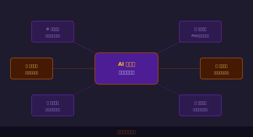
The following analysis breaks down the technical framework of intelligent crane anti-sway systems across five dimensions: core control principles, mathematical calculation of swing periods, AI applications in heavy-load scenarios, sensor data fusion, and routine maintenance troubleshooting.
Three Core Principles of Crane Anti-Sway Control Systems
Designing an effective anti-sway system goes beyond simple code implementation; it relies on rigorous physical and control theory foundations. In engineering practice, the Kelude Heavy Industry technical team has identified three fundamental principles necessary for efficient anti-sway performance, which form the underlying logic of modern intelligent control systems.
Principle 1: Input Shaping Feedforward Control. This approach modifies the spectrum of motor drive commands to avoid the natural frequency of the lifting spreader system. By doing so, it achieves zero residual vibration in an open-loop state, typically keeping system response latency under 50ms.
Principle 2: Closed-Loop Feedback Compensation. Since external disturbances such as wind loads and track irregularities exist in real-world conditions, feedforward control alone cannot eliminate all errors. Integrating high-precision sensors to create a closed-loop circuit allows PID or Fuzzy Logic Control algorithms to correct deviations in real-time, compressing steady-state error within ±5mm.
Principle 3: Model Predictive and Adaptive Adjustment. To address time-varying system parameters caused by load changes, the control system must possess online identification capabilities. It dynamically adjusts control parameters to ensure optimal sway suppression throughout the equipment's lifecycle.
"Input shaping technology modifies the spectrum of control commands to avoid the system's natural frequency, achieving zero residual vibration in open-loop states. This method has been widely validated in early overhead crane retrofits and serves as the cornerstone for complex anti-sway algorithms."
⚠️ Note
When applying input shaping, ensure that the mechanical transmission backlash of the crane is less than 2mm. Otherwise, rigid command modifications can cause mechanical shock, exacerbating fatigue damage to structural components and shortening service life.
Understanding these three principles clarifies why modern anti-sway systems require significant computing power. Next, we examine how algorithm engineers translate these concepts into precise mathematical models.
Calculating Physical Swing Periods for Lifting Spreaders
The swing period is the most critical foundational parameter in anti-sway algorithms. When writing control programs, the primary task for algorithm engineers is to establish an accurate physical model and calculate the system's natural period. For most bridge cranes, the lifting spreader system can be simplified as a single pendulum model.
The classic calculation formula for a single pendulum period is T = 2π√(L/g), where L is the effective length of the wire rope and g is the acceleration due to gravity (typically 9.8m/s²). While this formula appears simple, practical engineering requires comprehensive verification based on specific operating parameters.
Consider the following engineering case study to demonstrate the calculation process. Assume a workshop crane Long Travel Speed is 60m/min (1m/s). When braking to a stop with a deceleration rate of 0.5m/s², the braking distance s is calculated using kinematic formulas: s = v²/(2a) = 1²/(2×0.5) = 1m.
With the braking distance established, we return to the swing period calculation. If the effective wire rope length L is 10m, substituting into the formula yields T = 2 × 3.1416 × √(10/9.8) ≈ 6.34s. Algorithm engineers use this 6.34s value as a base parameter to design pulse sequence intervals in the input shaper. If operating condition changes increase the rope length to 15m, the period becomes 7.77s, requiring synchronous parameter updates in the algorithm.
"In practical engineering, discrepancies of approximately 3% to 5% often arise between pure rigid single-pendulum calculations and actual results due to uneven mass distribution of the lifting spreader and elastic deformation of the steel wire. These deviations must be compensated via online parameter identification, representing a key direction for algorithm optimization."
💡 Tip
When setting calculation cycles, engineers must match Variable Frequency Drive (VFD) acceleration and deceleration times. If the VFD ramp time is less than half a swing period, secondary sway may be excited, causing the anti-sway function to fail.
Precise period calculation is only the first step. The true challenge lies in applying this period to complex actual control strategies, which tests the depth of an algorithm engineer's expertise. Different control strategies exhibit significant differences in anti-sway effectiveness.
To intuitively understand these differences, the table below provides a multi-dimensional parameter comparison between traditional PID Control and AI-based Model Predictive Control.
📊 Comparison of Traditional PID Control and AI Model Predictive Control Performance
| control systemStrategy | Response time | steady-state error | anti-interference capability | ParameterAdaptive |
|---|---|---|---|---|
| ConventionalPID closed loop | 8~12Seconds | ±15mm | General | Requires manual retuning |
| AImodel predictive control | 2~4Seconds | ±3mm | Extremely strong | Online automatic learning |
AI-Driven Anti-Sway Algorithms for Heavy Load Conditions
When a Bridge Crane operates under heavy load conditions, system nonlinearity becomes pronounced. Factors such as wire rope elasticity, eccentric mass distribution of the lifting spreader, and rail friction during long travel often cause traditional linear control models to fail. In these scenarios, the advantages of an AI-based anti-sway algorithm become critical.
Kelude Heavy Industry recently integrated reinforcement learning-based anti-sway algorithms into a 50t overhead crane project. The project required stable operation even with crosswind interference reaching 12m/s. By leveraging AI, the final swing angle of the lifting spreader was strictly suppressed to within 1.5°.
The core strength of this AI algorithm lies in its robust feature extraction and generalization ability. During model training, the system processes vast amounts of operational data, including motor current, speed curves, and sensor feedback angles across various loads. After more than 5,000 iterations, the AI model accurately predicts future motion trajectories and proactively outputs reverse compensation commands.
This predictive control mechanism not only improves positioning efficiency but also significantly reduces impact loads on mechanical structures. For heavy-duty equipment, this translates to lower maintenance costs and extended service life.
"Measured data from a port project indicates that after introducing reinforcement learning algorithms, the anti-sway response time under rated load decreased by 42%, while anti-interference capability against sudden crosswinds improved by 30%, fully meeting the demands of high-frequency loading operations."
⚠️ Note
Training data for AI models must cover over 80% of operating conditions across the full stroke of the crane. If data is collected only under no-load or light load conditions, the model will suffer from severe overfitting under heavy load conditions, leading to divergent control commands.
The superior performance of AI algorithms relies on precise perception from underlying hardware. Without high-quality data input, even the most advanced algorithms are ineffective. This highlights the critical importance of sensor selection and data fusion.
For sensor selection and data fusion in complex operating conditions, different solutions show significant differences in cost and accuracy. Specific parameters are detailed in the table below.
📊 Technical and Economic Comparison of Mainstream Anti-Sway Sensor Solutions
| SensorType | measurement principle | TypicalAccuracy | environmental adaptability | total cost |
|---|---|---|---|---|
| HighAccuracyinclinometer | MEMSAddspeed/gyroscope | ±0.05° | Affected by high frequencyvibrationInfluence | Medium |
| Machinevision system | Image feature point tracking | ±0.1° | Affected by dust/Lighting constraints | Relatively high |
| LaserRadar Ranging | TOFTime of flight | ±2mm | Extremely strong | High |
Sensor Selection and Multi-Source Data Fusion for Anti-Sway Systems
In anti-sway systems, relying on a single sensor often fails to balance dynamic response with static accuracy. For instance, the drum encoder captures high-frequency trolley displacement changes but cannot directly perceive the lifting spreader's swing angle. Conversely, while inclination sensors measure absolute angles, they are susceptible to interference from inertia forces generated during trolley acceleration and deceleration.
To resolve this contradiction, multi-source data fusion technology has emerged. The system typically fuses encoder data sampled at 1000Hz with inclination sensor data boasting a resolution of 0.01°. By applying the Extended Kalman Filter (EKF) algorithm, the system filters out high-frequency noise and low-frequency drift, outputting smooth and precise state estimates.
In advanced applications, machine vision is introduced as a third data source. With latency controlled within 20ms, the vision system provides global positioning information for the lifting spreader, effectively correcting cumulative errors from local sensors. This multi-modal fusion architecture significantly enhances system robustness.
"Multi-source data fusion technology, utilizing the Extended Kalman Filter (EKF) algorithm, integrates the high-frequency dynamic data from encoders with the low-frequency absolute position data from inclination sensors. This reduces the overall system state estimation error to within 0.5°, providing a reliable data foundation for upper-level control algorithms."
💡 Tip
In harsh workshop environments with dust concentrations exceeding 10mg/m³, do not rely solely on machine vision sensors for angle measurement. Always add LiDAR or physical inclination sensors as redundant backups to prevent system loss of control due to visual blind spots.
No matter how sophisticated the algorithms and sensors are, they depend on standardized installation and regular maintenance. The degradation of hardware status can directly lead to the failure of algorithmic models; therefore, establishing a comprehensive maintenance system is key to ensuring the long-term stable operation of the anti-sway system.
Daily Maintenance and Common Fault Troubleshooting Guide for Crane Anti-Sway Devices
Routine maintenance of the anti-sway system focuses on three dimensions: sensor calibration, mechanical component lubrication, and electrical circuit inspection. For inclination sensors, it is recommended to perform appearance cleaning and zero calibration every 30 days of operation to ensure the mounting base is secure and free of looseness.
Regarding electrical checks, the 24V DC power supply inside the Control Cabinet serves as the system's power source. Maintenance personnel should regularly measure the supply voltage, ensuring fluctuations remain within ±10% of 24V. Additionally, use a Megohmmeter (Insulation Tester) to check the insulation resistance of motors and cables; the resistance value must exceed 5MΩ to prevent leakage current from interfering with control signals.
When the system exhibits abnormal swinging, fault diagnosis should follow the principle of "mechanics before electricity, hardware before software." First, inspect the Wire Rope for severe wear or wire breakage. Second, check if the rail joint gap exceeds standards. If the mechanical parts are normal, use commissioning software to verify whether the sensor data shows any jumps or anomalies.
Notably, the frequent high-frequency operations of the anti-sway system may exacerbate stress concentration at the Main Girder connection points. Therefore, during routine inspections, combine weld crack detection technology to regularly assess the health status of structural components, preventing issues before they arise.
"The Maintenance Manual explicitly states that the inclination sensors in the anti-sway system require zero calibration every 2000 hours of operation. If the zero deviation exceeds 0.1°, it will directly cause steady-state error in the PID closed loop, resulting in the lifting spreader maintaining a slight continuous swing even after stopping."
⚠️ Note
When troubleshooting electrical faults, if you find that the 24V DC power supply voltage fluctuates by more than ±2V, prioritize checking if the filter capacitors are aging or bulging. Do not replace the mainboard directly to avoid secondary damage and unnecessary cost waste.
In summary, crane anti-sway technology has evolved from simple mechanical damping to complex control systems integrating AI algorithms and multi-source sensing. From precise calculation of the swing period to model prediction under heavy load conditions, every step requires rigorous engineering practice. Kelude Heavy Industry has accumulated rich practical experience in heavy-load customization, providing clients with full lifecycle solutions ranging from underlying algorithm optimization to complete machine system integration, helping enterprises achieve intelligent upgrades in material handling.
FAQ
Q: What is the core difference between traditional anti-sway and AI-based anti-sway?
A: Traditional anti-sway relies heavily on fixed mathematical models and PID closed-loop control, making it sensitive to parameter changes. AI-based anti-sway uses machine learning algorithms to automatically adapt to non-linear factors such as load variations and wind speed interference. It offers stronger self-learning capabilities and robustness, showing more significant effects in suppressing residual vibrations, especially under complex operating conditions.
Q: What sensor data do algorithm engineers need to collect when calculating the swing period?
A: The primary data required includes the effective length of the steel wire rope and the real-time inclination angle of the lifting spreader. Length data is typically calculated via the drum encoder, while the inclination angle relies on high-precision inclination sensors or the vision system. These two sets of data form the basic input for building the pendulum model and performing online parameter identification.
Q: What is the approximate budget for upgrading an existing crane with an AI anti-sway system?
A: The upgrade budget is significantly influenced by the crane's capacity, span, and the compatibility of the existing electrical system. Costs typically include sensor hardware, the AI Control Cabinet, and software licensing fees. The specific amount needs to be assessed based on the Technical Solution following a Site Survey. The final Quotation is subject to the actual contract, and it is recommended to reserve a 15% safety margin for commissioning.
Q: Does the installation of Anti-Sway System Sensors on the crane Main Girder have specific requirements?
A: Yes, there are strict requirements. The Sensor installation position must avoid local resonance zones of the Main Girder, and the Stiffness of the mounting base must meet the standard. If the base undergoes elastic deformation, it introduces structural error into the collected Angle data, which compromises the Accuracy of the algorithm’s calculation of the actual swing period.
