

Grab Bucket Design: 4 Critical Parameters to Prevent Failures
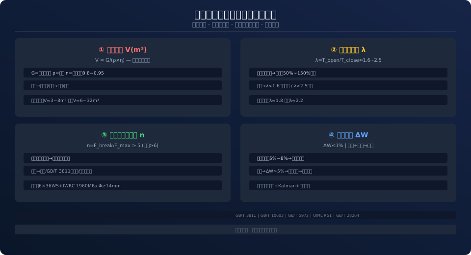
Grab bucket design hinges on four parameters, each as delicate as walking a tightrope—undersize the volume and the bucket comes up short, miscalculate the open-close tension ratio and you snap the wire rope, cut the safety factor too close and the inspection authority will flag it, and let the weighing drift and the boiler combustion starts to fluctuate. These four parameters are not independent variables; get one wrong and the other three are effectively wasted.
Grab Bucket Volume: More Than Just "Lifting Capacity ÷ Density"
The basic formula is V = G/(ρ×η). But all three variables shift constantly—waste density ranges from 0.4 to 0.9 t/m³, and the fill coefficient from 0.6 to 0.95. Proper design doesn't rely on average values; it calls for boundary-condition verification: minimum density × minimum fill coefficient yields the maximum bucket volume (ensuring no overload), while maximum density × maximum fill coefficient gives the minimum bucket volume (ensuring the feed rate is met). Per ISO 4301, the grab's dead weight typically runs 35%–50% of the rated lifting capacity—an oversized bucket that pushes the dead weight beyond limits requires re-verification of the bridge beam's strength and stiffness.
Open-Close Rope Tension Ratio: The Parameter Most Often Guessed
λ = open-close rope tension / support rope tension, with a theoretical range of 1.6–2.5. This ratio is not constant—it varies with the opening angle: at the start of closing, λ ≈ 1.2 (just overcoming dead weight), then climbs rapidly to 1.8–2.2 as the grab bites into the material, and can exceed 2.5 during the final 5°–10° of compaction. Designing with a constant high λ results in excess force early in the closing cycle, causing the grab shells to slam into the material with excessive acceleration. The correct approach is dual-mode control: low pressure at the start of closing (λ ≈ 1.5), medium pressure in the middle (λ ≈ 2.0), and full pressure at the end (λ ≈ 2.5), requiring the hydraulic system to be fitted with a proportional pressure reducing valve and an angle sensor, managed through PLC split-range control.
Wire Rope Safety Factor: The Inspection Authority Only Accepts Numbers
| Parameter | Requirements | Description |
|---|---|---|
| support rope | ≥5.0 | ISO 4301 Crane Design Standard Table30, M5~M6 |
| open close Rope | ≥6.0 | Higher Alternating Stress |
| Recommended Rope Type | 6×36WS+IWRC | Independent Wire Rope Core (IWRC)1960MPa Φ≥14mm |
The open-close rope undergoes one complete fatigue cycle per operation—at 120 cycles per day, that's 43,000 cycles per year, and 430,000 cycles over 10 years, exceeding the wire rope fatigue limit (200,000–300,000 cycles). The rope will need to be replaced at least 2–3 times over its service life. The safety factor is set at 6.0 rather than 5.0—that extra 1.0 is buying time for fatigue life.
④ Load Cell Drift: A Small Issue with a Big Impact on Boiler Efficiency
Wire rope elastic elongation (a 20 m rope stretches 30–50 mm between full load and empty) combined with grab closure vibration (2–5 Hz) generates sensor noise reaching 5%–8% of full scale. Solution: triaxial acceleration compensation + Kalman filtering + automatic calibration every shift. The Kalman filter estimates true weight amid vibration noise (referencing OIML R51), and per-shift automatic calibration compensates for zero drift (0.3%–0.5% per day under high-frequency use).
How the Four Parameters Interact
A larger bucket volume increases dead weight, which lowers the safety factor, which demands a larger-diameter wire rope and drum, which enlarges the mechanism, which requires a stronger main girder, which drives up investment. Grab design is essentially about finding the optimal point on this chain of trade-offs—typically requiring 3–4 iterations to converge. Each iteration must re-pass GB/T 28264 safety monitoring verification and JB/T 11184 functional inspection.
Design Calculation Example: Full Verification of a 10 t Refuse Grab
The following uses a 10 t four-rope feeding grab for a 600 t/day waste-to-energy power plant as an example, walking through the complete verification of the four key parameters.
Given conditions: Rated lifting capacity G = 10 t, grab dead weight G0 = 4 t (40% of rated capacity), effective payload Ge = 6 t. Refuse density range ρ = 0.4–0.9 t/m³ (after fermentation), fill factor η = 0.85, lifting height H = 18 m, traverse distance L = 35 m. Work duty M6, 6,500 operating hours per year, design life 15 years.
Volume verification: V = Ge/(ρ × η). Check maximum bucket volume at minimum density: Vmax = 6/(0.4 × 0.85) = 17.6 m³—at this volume, grab + material total weight = 4 + 17.6 × 0.4 = 11.04 t > 10 t, overloaded! The volume must be reduced. Change to V = 8 m³: total weight = 4 + 8 × 0.4 = 7.2 t 6 t, close to the rated value, with tight margin. Final bucket volume is 8 m³, but when grabbing raw refuse (60% moisture + density 1.0 t/m³), the fill factor must be limited to 0.65, keeping single-cycle payload ≤ 8 × 1.0 × 0.65 = 5.2 t 0.65 = 5.2 t < 6 t to prevent overload.
Tension ratio verification: For refuse type, λ = 1.8. Maximum open-close rope tension = F_close_max = (Ge × g) × (λ−1)/λ = (6 × 9.81) × 0.8/1.8 = 26.2 kN. Maximum support rope tension = F_support = G × g = 10 × 9.81 = 98.1 kN. Combined rope load = 124.3 kN. With a 1.25 dynamic load factor applied = 155.4 kN.
Wire rope selection: Minimum breaking force required for the open-close rope = 155.4 × 6.0 = 932.4 kN. Select 6×36WS+IWRC-1960MPa-Φ16mm wire rope, standard breaking force = 178 kN—insufficient! Upgrade to Φ22mm: breaking force = 336 kN, safety factor = 336/26.2 = 12.8 > 6.0, OK but oversized. Φ20mm breaking force = 278 kN, safety factor = 10.6, OK and reasonable. For the support rope, take a safety factor of 5.0: Φ20mm gives 278/98.1 = 2.8—insufficient! Must upgrade to Φ26mm: breaking force = 468 kN, safety factor = 468/98.1 = 4.8
Weighing system design: Use a 10 t capacity S-type load cell (accuracy class C3, 3,000 divisions) paired with a triaxial MEMS acceleration sensor (±16 g range) for inertial force compensation. Kalman filter parameters: process noise covariance Q = 0.01, measurement noise covariance R = 0.1. Calibration schedule: automatic zero calibration every shift + standard test weight verification weekly. Measured dynamic accuracy: static ±0.05%, dynamic (normal grabbing conditions) ±0.8%, dynamic (rapid start/stop) ±1.5%—all within the acceptable ±2% range.
FEA: Critical Zones and Typical Results
Finite element analysis of a grab should not be approached as "throw the whole grab into FEA software and see where the stress goes"—full-model analysis of this kind is both time-consuming and inaccurate. The correct approach is to focus on three stress concentration zones and build refined sub-models for each.
Stress concentration zone 1: the jaw hinge pin. This is a short, stout pin operating under combined shear and bending loads. Under eccentric loading (when the grab hits a hard object on one side only), the bending moment on the pin can reach 2.5–3 times that of symmetric loading. FEA results show the maximum stress point is not at the pin center (as intuition would suggest) but at the edge where the pin contacts the lug plate—a classic Hertzian contact stress concentration. Solution: induction hardening of the pin surface to HRC 50–55, press-fit hardened steel bushings in the lug plate bores, and pin diameter rounded up from 1.2 times the calculated value.
Stress concentration zone 2: the hydraulic cylinder lug seat. The lug seat weld carries the full closing force at peak pressure during the final stage of jaw closure. FEA results show a stress concentration factor of approximately 15%–20% at the weld root—but if the weld is not full penetration, this factor jumps to 40%–50%. This is why the hydraulic cylinder lug seat welds on hazardous waste grabs must undergo 100% ultrasonic testing (UT), not just magnetic particle inspection (MPI) for surface defects. UT detects incomplete fusion and porosity inside the weld; MPI only reveals surface cracks.
Stress concentration zone 3: the tooth tip root and shell transition zone. This area absorbs impact loads when grabbing material containing large hard objects, and the R-radius at the tooth tip root directly determines the degree of stress concentration. Parametric FEA analysis: increasing the R-radius from 2 mm to 8 mm reduces maximum principal stress by approximately 45%. Recommended minimum R-radius at the tooth tip root: 4 mm. Tooth tips with an R-radius below 2 mm carry a micro-crack risk within 5,000 cycles.
Frequently Asked Questions
Q: What percentage of rated lifting capacity should the grab's dead weight be? A: Typically 35%–50%. Four-rope grabs tend toward the lower end; hydraulic grabs toward the higher end. If dead weight exceeds 50%, consider: whether the main girder is designed for the extra load, and the fact that every 1 t of additional dead weight reduces payload by 1 t—for a 10 t grab, that's a 10% efficiency loss. Q: Can the support rope and open-close rope be the same specification? A: Not recommended. The support rope carries static load; the open-close rope carries dynamic load. Using the same specification leads to: accelerated wear from reduced contact area on the drum groove for the open-close rope, and increased system inertia from a larger drum that slows open-close speed. If the open-close rope is undersized, fatigue life falls short. Q: Is FEA necessary for grab design? A: It is mandatory for the three stress concentration zones: the jaw hinge area, the hydraulic cylinder lug seat, and the tooth tip root. In particular, the hinge pin under eccentric loading can experience bending moments 1.5–2 times the design value. Designing with uniform cross-sections without FEA can result in localized overstress while the overall safety factor still looks adequate—the most dangerous false sense of safety. Q: How much error can the weighing system be controlled to? A: Static calibration ±0.1%, comprehensive error under actual operating conditions (vibration + rope sway + temperature drift) ±1%–±2%. Boiler feeding allows ±3% as acceptable. For higher precision, a separate static weighing system is required (weighing on the ground before lifting), but cycle time increases from 6 minutes to 9–10 minutes. For grab design calculation and optimization, please consult the Kelude Heavy Industry technical team—full-process support from concept validation to FEA analysis. still looks adequate—the most dangerous kind of false security.
Q: What level of weighing accuracy can be achieved?
A: Static calibration achieves ±0.1%; combined error under real operating conditions (vibration + rope sway + thermal drift) is ±1%–±2%. For boiler feeding, ±3% is acceptable. Higher accuracy requires a separate static weighing system (weighing the grab while it rests on the ground before lifting), but cycle time increases from 6 minutes to 9–10 minutes.
For grab design calculations and optimization, contact the Kelude technical team—full support from concept review to FEA analysis.
