

Vision Recognition in Lifting Operations
Visual recognition technology is rapidly becoming the core driver of intelligent hoisting operations. By leveraging multi-channel high-definition cameras and deep learning algorithms, these systems achieve a recognition accuracy exceeding 95% for lifting spreaders and obstacles, with system response times controlled within 0.2 seconds. Industry statistics indicate that workshops adopting this technology have reduced collision accidents caused by blind spots by approximately 30%. This article provides a comprehensive analysis of the technology's applications in anti-collision and anti-sway scenarios, alongside cost accounting and maintenance considerations, to serve as a practical reference for engineering professionals.
When designing the hardware layout and logic control of visual recognition systems, it is essential to strictly adhere to the electrical control and safety protection regulations outlined in FEM 1.001 Crane Design Standard, while meeting the specific requirements for Safety Monitoring and Management Systems defined in TSG 51-2023 Crane Safety Technical Supervision Regulation. These standards ensure that visual data can be reliably integrated into the crane's safety circuit, achieving inherent safety.
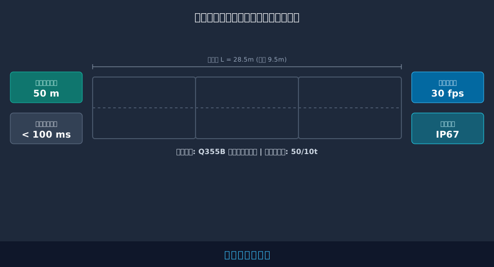
The following sections detail the practical application and engineering precautions of crane visual recognition technology across five dimensions: anti-collision safety distance control, anti-sway installation processes, cost accounting and equipment selection, joint maintenance troubleshooting, and comprehensive performance evaluation.
Optimizing Anti-Collision Safety Distances via Visual Recognition
In large workshops or environments involving cross-operation between multiple cranes, collision prevention is a top priority in safety management. Traditional mechanical limit switches or laser distance measurement devices are often susceptible to interference from dust and vibration in complex settings. In contrast, visual recognition technology extracts image features to calculate spatial three-dimensional distances with greater precision. For detailed technical insights on setting safe distances and logic control, refer to our guide on anti-collision safety distance; the vision system builds upon these principles to provide more intuitive image-based early warning.
Consider a 50-ton double-girder crane in a heavy equipment manufacturing workshop. Its Long Travel Speed is set at 60m/min (1m/s). When the vision system detects an obstacle ahead and triggers a deceleration command, the system applies a deceleration rate of 0.5m/s². Using the kinematic braking distance formula s=v²/(2a), the theoretical braking distance is calculated as s=1²/(2×0.5)=1m. Consequently, the system must issue the deceleration command at least 1.5m away from the obstacle (incorporating a 0.5m safety margin) to ensure the lifting spreadler stops smoothly without collision. The system's effective recognition range is set to 50m, providing ample lead time for algorithm processing.
"Measured data shows that under well-lit conditions, the vision recognition system can identify standard container profiles at distances ranging from 45m to 50m, with distance calculation errors controlled within ±5cm. This fully meets the anti-collision requirements during high-speed bridge travel."
During system deployment, attention should be paid to two key points:
First, camera installation positions must avoid obstruction by the main girder web plate to ensure field of vision coverage extends across the entire bridge runway rail, preventing visual blind spots.
Second, the computing power of the vision processing unit must support concurrent processing of multiple video streams to prevent frame lag and subsequent command latency.
⚠️ Precautions
In casting or grinding workshops, suspended metal dust easily adheres to camera lenses, reducing recognition rates. We recommend scheduling professional lens cleaning every 15 days or installing protective covers equipped with automatic wipers and pneumatic purging functions.
Anti-Sway Algorithm Installation for Complex Operating Conditions
Lifting spreader sway not only reduces hoisting efficiency but also increases fatigue damage to structural components and raises the risk of load detachment. Vision-based anti-sway systems track high-contrast keypoints on the hook in real-time, combined with AI anti-sway algorithms, to achieve closed-loop control of trolley and bridge travel. The core of this process lies in precise camera calibration and dynamic adjustment of algorithm parameters.
During installation, cameras are positioned beneath the Trolley Frame, approximately 3.5m above the highest point of the hook, with a pitch angle set to 45 degrees. The system requires a minimum frame rate of 30fps to clearly capture keypoints even during rapid movement. In emergency stop tests with a full load of 30 tons, the initial sway angle was approximately 2.5 degrees. After intervention by the vision algorithm, fine-tuning of the motor frequency suppressed the sway amplitude to within 0.2 degrees in just 3 seconds, significantly improving micro-motion positioning efficiency.
"On-site commissioning records indicate that after implementing vision-based anti-sway technology, the average cycle time per single hook operation decreased by 12 seconds. For high-frequency workshops executing 200 hooks daily, this results in a significant boost in overall production capacity."
When configuring algorithm parameters, observe the following guidelines:
First, input the accurate rope reeving ratio based on the actual lifting spreader length; otherwise, the algorithm cannot establish a correct physical sway model.
Second, in areas with direct strong sunlight or highly reflective metal panels on the workshop ceiling, enable the Wide Dynamic Range (WDR) function on the camera to prevent overexposure and loss of keypoints.
💡 Tip
Vision anti-sway algorithms are sensitive to wire rope torsion. If the wire rope suffers from severe knotting or plastic deformation, the center of gravity of the hook will shift. In such cases, perform Wire Rope Replacement first, followed by re-calibration of the vision zero point.
Cost Accounting and Equipment Selection for Intelligent Retrofit Projects
For enterprises undergoing intelligent upgrading, cost and equipment selection are critical decision-making factors. Kelude Heavy Industry typically evaluates the total cost—including hardware procurement, software licensing, construction commissioning, and ongoing operation and maintenance—when providing customized solutions, ensuring the return on investment aligns with expectations. Proper selection strategies not only meet current operational needs but also reserve interfaces for future functional expansion.
Consider a standard Double Girder Crane with a Span: 28.5m (93.5 ft) and Lifting Capacity: 50/10t. Retrofitting it with a Vision Recognition System—including four industrial cameras, an edge computing gateway, and anti-collision / anti-sway modules—requires an initial investment of approximately $22,335. While this represents a ~40% increase over traditional mechanical-only solutions, the vision system consolidates multiple functions and eliminates the need for frequent replacement of worn mechanical parts. With estimated annual maintenance savings of $2,978, the return on investment is achieved in roughly 2.5 years. Final project costs are subject to the actual contract.
To clearly illustrate the economic differences between these approaches, we have compiled the following cost comparison:
📊 Total Cost Comparison: Traditional Limit Switches vs. Vision Recognition Systems
| Comparison Parameter | ConventionalMachinery/Laserlimit switchSolution | IntelligentVision Recognition SystemSolution |
|---|---|---|
| Initial Hardwareprocurement cost | Approx. 4.510,000 RMB | Approx. 1210,000 RMB(Includingcomputing powergateway) |
| Software License andCommissioningFee | 0.510,000 RMB | 310,000 RMB(IncludingAIAlgorithm License) |
| Annual AveragemaintenanceCost | Approx. 1.210,000 RMB(Wear Partsreplacement) | Approx. 0.410,000 RMB(Mainly for Cleaning andCalibration) |
| Functional Scalability | Poor,Capable Only of Single Anti-Collision | Strong,Stackableanti-sway control、Zone Exclusion, etc. |
After evaluating initial investment and long-term returns, equipment selection must prioritize system Stability and compatibility. These factors directly determine the efficiency of fault diagnosis and the maintenance cycle.
The table below details common faults encountered by the vision system during operation and their standard troubleshooting cycles, assisting device management in developing an effective maintenance plan.
📊 Common Faults and Troubleshooting Cycles for Vision Recognition Systems
| fault symptom | possible cause | recommendationtroubleshooting/maintenance cycle |
|---|---|---|
| Blurred Image/IdentificationRateLowering | Lens Dust Accumulation、Condensation | Every 30Day Clean Lens Once |
| distanceLarge Calculation Error | Physical Displacement of Camera、CalibrationParameterLoss | Re-calibrate Every Half Yearzero calibration |
| Frequent Systemfalse alarmAlarm | BackgroundenvironmentSudden Light Change、electromagnetic interference | QuarterlyinspectionShielded CableGroundingCondition |
"Industry research indicates that companies strictly implementing the above maintenance cycles can keep annual vision system fault downtime to less than 8 hours, boosting overall equipment utilization by 15%."
⚠️ Note
When selecting an edge computing gateway, avoid choosing models with just enough computing power to save budget. We recommend reserving a 30% computing power redundancy to accommodate future AI model upgrades or additional camera integrations.
Joint Maintenance and Fault Diagnosis for Vision Sensors and Main Girder Weld Crack Detection
The application of vision systems extends beyond dynamic operational monitoring; it integrates seamlessly with structural health monitoring. For instance, by equipping high-resolution industrial cameras with specialized image enhancement algorithms, the system provides high-precision image data support for weld crack detection, enabling multi-dimensional equipment health management. This joint maintenance approach significantly reduces the risks associated with manual high-altitude inspections.
In joint inspection mode, cameras must automatically patrol to critical stress nodes on the main girder (such as the junction of the mid-span bottom flange and web plate) during crane idle periods. The system requires an image resolution of over 5 megapixels to clearly capture tiny surface cracks narrower than 0.2mm. Furthermore, the mounting brackets for vision sensors must possess extreme rigidity to ensure calibration error remains within <2mm under long-term vibration. Through this joint monitoring, early equipment failure rates can be reduced by approximately 40%.
Technicians should follow these procedures when conducting joint maintenance:
Step 1: Inspect the working condition of camera lenses and fill lights to ensure uniform illuminance in weld areas, free from severe shadow interference.
Step 2: Compare against historical image databases, using algorithms to automatically annotate suspected crack propagation areas and generate trend reports.
"After adopting joint vision inspection technology, a Port Terminal successfully identified a fatigue micro-crack approximately 15mm long in the main girder web plate at an early stage, preventing potential major structural failure incidents."
💡 Tip
Vision-based crack detection cannot replace non-destructive testing methods such as ultrasonic or magnetic particle inspection. It is primarily used for trend monitoring and early warning of macroscopic surface cracks. Upon detecting anomalies, professional personnel must still be arranged to conduct in-depth non-destructive testing for confirmation.
Comprehensive Performance Evaluation and Optimization of Crane Vision Recognition Systems in Heavy Load Environments
In severe working conditions characterized by heavy loads, high temperatures, or high humidity, the comprehensive performance of vision recognition systems faces rigorous tests. The system must maintain extremely low computational latency to ensure the real-time performance of control commands while guaranteeing recognition accuracy. When delivering such heavy-load customized equipment, Kelude Heavy Industry conducts strict environmental adaptability testing and performance evaluation for the vision system.
Evaluation data shows that under standard operating conditions, the system's comprehensive recognition accuracy reaches 98.5%. However, when ambient illuminance drops below 50Lux (such as during nighttime outdoor operations or emergency power outages in factory buildings), the performance of visible light cameras decreases significantly. In such cases, the system must automatically switch to infrared thermal imaging mode or activate auxiliary fill lights. Optimized systems strictly control the overall latency—from image acquisition and algorithm processing to outputting control signals—to less than <100ms, fully meeting the stringent requirements for braking response in heavy-load hoisting mechanisms.
To maintain efficient system operation, optimization efforts should focus on the following aspects:
On one hand, regularly clean the Cooling Fan filters of the edge computing gateway to prevent CPU throttling due to excessively high Ambient Temperature, which would increase processing latency.
On the other hand, timely update and train AI recognition models based on changes in Hoisting materials, ensuring that the system's recognition accuracy for new cargo profiles does not attenuate.
"In continuous tests within a summer workshop with high Ambient Temperature (45℃), the vision gateway equipped with an industrial-grade heat dissipation module maintained its core board temperature below 65℃, with no instances of shutdowns or restarts caused by overheating."
⚠️ Note
In areas with strong thermal radiation, such as smelting workshops, cameras must be fitted with water-cooled or air-cooled thermal insulation protective covers. Otherwise, high temperatures will not only damage the Sensor but also cause drastic changes in the refractive index of the air in front of the lens, resulting in severe image distortion.
FAQ
Q: What are the specific requirements for site lighting conditions for crane vision recognition systems?
A: The system typically requires the illuminance in the operational area to be between 100Lux and 1000Lux, with uniform light distribution. Direct exposure of cameras to strong light sources or sunlight should be avoided. In low-light environments where illuminance is below 50Lux, auxiliary fill lights should be activated or the system switched to infrared thermal imaging mode to ensure recognition accuracy.
Q: What are the Protection Rating (IP), Resolution, and power consumption specifications for industrial vision cameras?
A: Industrial-grade cameras typically feature an IP67 Protection Rating (IP), ensuring reliable operation in dusty or washdown environments. Resolutions generally range from 4 to 5 megapixels to capture critical details with clarity. Peak power consumption per camera unit, including fill light, is typically between 15W and 25W, having a negligible impact on the crane's total electrical load.
Q: What are the estimated renovation costs and ongoing maintenance expenses after implementing a Vision Recognition System?
A: For a standard Double Girder Crane, the retrofit cost—including hardware, algorithm licensing, and commissioning—is approximately $22,335 (subject to the actual contract). Routine maintenance primarily involves periodic cleaning and Calibration, with annual maintenance costs ranging from $595 to $2,978. This is significantly lower than the replacement frequency and associated costs of traditional mechanical limit switches.
Q: How does the vision system integrate with existing PLC Control Systems for data exchange?
A: The Edge Computing gateway typically connects to the crane's main PLC via industrial Ethernet protocols such as Profinet or EtherCAT. The system packages identification data—such as distance and Angle parameters—into standard message frames and transmits them to the PLC in real-time at millisecond intervals. The PLC then processes this input to generate control commands for the Frequency Inverter / VFD.
In summary, visual recognition technology offers significant advantages in anti-collision, Anti-sway control, and structural Monitoring, effectively enhancing operational safety and efficiency. However, optimal application effect relies heavily on proper selection, standardized installation, and rigorous routine maintenance. Kelude Heavy Industry leverages its deep expertise in heavy load lifting equipment to provide a one-stop solution—from custom vision system development and algorithm tuning to full-machine integration. We ensure intelligent transformation technologies are successfully implemented under complex operating conditions, empowering enterprises to achieve true digital maturity.
