

Non-Standard Crane Design Guide: Low-Temp, Corrosion, Rail & Control
9 Practical Guides to Non-Standard Crane Design: Low-Temperature Anti-Corrosion, Profiled Rails, Smart Controls, and Industry-Specific Machines. Non-standard customization is a core capability in crane engineering.
Non-standard customization is a core capability in crane engineering. Extreme environments, special structures, industry-specific machines, and unusual loads that standard models cannot cover require a tailored approach across four dimensions: structural design, material selection, electrical control, and system integration. Drawing on years of non-standard project experience, Kelude has systematically compiled nine of the most representative design scenarios, covering low-temperature anti-corrosion, offset lifting configurations, circular rails, remote-control retrofits, anti-collision systems, nuclear power plant polar cranes, shipyard VFD drives, and lifting spreaders for extra-long workpieces. Each guide includes technical principles, engineering parameter tables, and an FAQ section, providing a complete reference for the design, selection, and acceptance of non-standard cranes. This collection references more than 15 national and industry standards, including ISO 4301 Crane Design Standard, FEM 1.001, and NB/T 20013, and covers 32 calculation parameters across a lifting capacity range of 5t to 250t, with operating temperatures from -40°C to +60°C and anti-corrosion classes from C3 to marine-grade. It applies to steel structure workshops, cold storage facilities, chemical plants, nuclear power plants, shipyards, and ports.
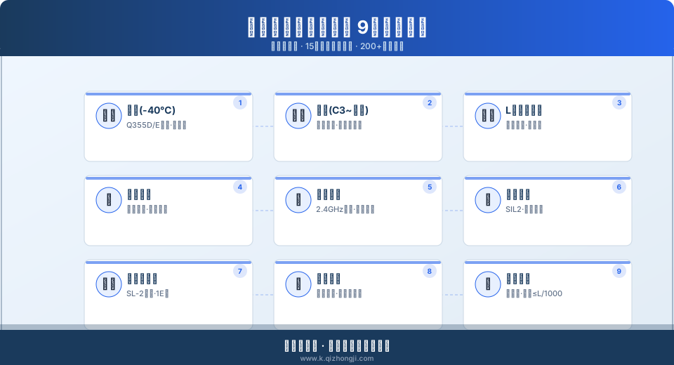
Series Overview: 9 Non-Standard Crane Design Scenarios
| Special Topic | Direction | Core Content |
|---|---|---|
| 1 | Extreme Environment-Low Temperature | -40℃Cold Storage Dutycrane, structural steel Material Low-Temperature Embrittlement, Grease Selection, Electrical Component Protection |
| 2 | Extreme Environment-Anti-corrosion | C3/C5/Offshore Grade IIIAnti-corrosion Solution, Coating / painting System, Stainless Steel Material Selection, Sealing Design |
| 3 | Special Structure-Offset Suspension | L-Type Offset Gantry Crane Outrigger Design, Long Material Largeclearance Force Calculation |
| 4 | Special Structure-Ring Rail | circular railcrane Wheel Self-Aligning, arc track Manufacturing, Multi-Crane Collision Avoidance Control |
| 5 | Customized Functionality-Remote Control | Legacycrane Wireless Retrofit: Remote Control Retrofit, Video Monitoring, Automatic Positioning All-in-One Solution |
| 6 | Customized Functionality-Anti-Collision | Multiple Cranes on Same Span Anti-Collision System, Li DAR+PLCInterlock+zone limit Three-Tier Protection |
| 7 | industry-specific machine-nuclear power | nuclear power plant ring travel crane seismic calculation, radiation-proof sealing, Fail-Safe Braking |
| 8 | industry-specific machine-Shipyard | Portal crane Variable Frequency Drive (VFD)Retrofit, Hoisting/Luffing/Slewing Three Mechanisms Synchronization Commissioning |
| 9 | Load Special-Long Goods | 20m Ultra-Long Workpiece Specific Lifting Spreader, Spreader Beam Design and Stress Verification |
Special Topic 1: Cold Storage Crane – Custom -40°C Solution
Read more: Custom Cold Storage Crane for -40°C Environments
Cold storage environments impose extremely demanding requirements on crane steel structures and electrical systems. At -40°C, standard Q235B carbon steel has a ductile-to-brittle transition temperature (approximately -20°C) far above the operating temperature, with impact absorption energy dropping sharply from ≥27J at room temperature to ≤5J, creating a risk of brittle fracture. This special topic systematically covers three key design considerations: low-temperature steel selection (Q355D/E grade, impact energy ≥27J at -40°C, measured at 34J), low-temperature grease (synthetic hydrocarbon base, pour point ≤-55°C, low-temperature torque ≤0.3N·m), and electrical component protection (heating tape power density 0.3W/cm² plus sealed enclosure rated IP55). It also provides the engineering rule-of-thumb that hoisting motor power at -40°C must be oversized by 1.2× compared to room-temperature selection, along with an anti-icing treatment solution for rail joints at cold storage doorways (heat tracing tape at 15W/m plus stainless steel conductor rail), ensuring an annual failure rate of ≤0.5 incidents per unit.
Special Topic 2: Three-Tier Anti-Corrosion Coating Systems for Cranes
Read more: Custom Anti-Corrosion Crane Coating Systems
Corrosive environments—marine atmospheres (salt spray deposition rate ≥300mg/m²·d), acid/alkali plants (pH 2–5), and galvanizing facilities (ammonium chloride atmosphere at 400°C)—demand differentiated coating systems and material selection for cranes. This special topic systematically outlines three anti-corrosion protection levels: C3 (moderate corrosion, suitable for dry indoor environments, total coating thickness ≥160μm) indoor environments, total coating thickness ≥160μm), C4 (high corrosion, suitable for chemical plants, total coating thickness ≥200μm)l plants, total coating thickness ≥200μm), and C5-I/CS (marine/industrial extreme corrosion) (extreme marine/industrial corrosion, total coating thickness ≥280μm). The coating system employs a three-layer structure: epoxy zinc-rich primer (zinc content ≥80%) + epoxy MIO intermediate coat + polyurethane topcoat. Stainless steel fasteners are selected to class A4-80, with 304/316 stainless steel grades determined by chloride ion concentration (≤1000ppm: 304; >1000ppm: 316). Electrical enclosure sealing ratings vary by installation location: IP55 for indoor, IP65 for outdoor, and IP66 for washdown areas. Salt spray test durations correspond to ≥480h for C3 and ≥720h for C5, with measured protective service life reaching 5–15 years.
Special Topic 3: Structural Design of L-Type Offset Gantry Cranes
Read more: Custom L-Type Offset Gantry Crane Design
Offset gantry cranes feature a curved L-shaped outrigger structure that creates a wide lateral clearance between the two legs (clearance width can reach 40%–60% of the span), specifically designed for handling extra-long materials such as steel pipes, rebar, H-beams, and plates. This special topic focuses on three major load characteristics of L-type outriggers: main girder torque increases by 30%–50% under eccentric loading, stress concentration factors at the outrigger base reach 1.8–2.2, and uneven wheel loads on one side of the rail cause maximum wheel load to reach 1.5× the average value. It provides outrigger cross-section optimization methods (box-section height-to-width ratio of 1.5–2.0, flange plate thickness ≥16mm), stiffener spacing ≤800mm, and the calculation procedure for selecting M36–M48 anchor bolts. The main girder deflection control target for offset gantry cranes is ≤L/750, with a safety factor of 1.48 and an overall anti-overturning stability coefficient ≥1.3.
Special Topic 4: Circular Rail Crane Design
Read more: Custom Circular Rail Crane Solutions
Circular rail cranes are used in nuclear power plant reactor buildings (building diameter φ37–φ45m), chemical plant circular tank farms (tank farm diameter φ20–φ60m), and similar applications where the crane travels along an arc track with a curvature radius typically of 10–30m. This special topic covers three core technologies: arc track manufacturing tolerances (track gauge deviation ≤±3mm, rail height difference ≤2mm/2m, arc deviation ≤2mm per 2m chord length), automatic wheel self-aligning mechanism design (tapered tread surface with 1:20 taper plus horizontal guide roller clearance of 5–8mm), and multi-crane collision avoidance control (zone interlocking + PLC multi-master ring fiber-optic communication with response time ≤100ms). Butt welds on circular rails must undergo 100% UT flaw detection plus 20% RT spot inspection in accordance with NB/T 47013.3-2015, followed by post-weld stress-relief heat treatment at 580–620°C. Overall slewing positioning accuracy is ≤±5mm.
Special Topic 5: Wireless Remote Control Retrofit for Legacy Cranes
Read more: Custom Retrofit Solutions for Aging Cranes
Many legacy cranes still in service rely on cab operation or ground-level push-button pendants, requiring operators to climb up and down frequently while facing blind spots and personal safety hazards. Industry statistics indicate that approximately 30% of crane safety incidents are directly related to obstructed operator visibility. This special topic presents a comprehensive wireless retrofit package: remote control installation using industrial-grade 2.4GHz frequency-hopping technology (transmit power ≤10mW, communication range ≥100m in open areas, ≥50 anti-interference channels), video monitoring system with wireless cameras plus cab display (1080P resolution, infrared night vision, IP65 protection), and automatic positioning using incremental encoders plus laser distance sensors (measurement accuracy ±2mm/30m). The integrated three-in-one solution has a retrofit period of 3–7 days, requires no modification to the existing electrical main circuit, and does not affect existing safety interlock devices. An auxiliary VFD retrofit enables continuously variable-speed control for all three mechanisms—hoisting, crane bridge travel, and trolley travel—with energy savings of approximately 25%–35%.
Special Topic 6: Anti-Collision Systems for Multiple Cranes on the Same Span
Read more: Custom Anti-Collision Solutions for Multiple Trolleys on One Span
Collision risk among multiple bridge cranes sharing the same span grows quadratically with the number of units—3 cranes on one span create C(3,2)=3 potential collision pairs, while 5 cranes create 10 pairs. This special topic designs a three-tier anti-collision protection system: Tier 1 uses LiDAR area scanning (detection range 0.5–20m adjustable, scan angle 270°, protection rating IP67, response time ≤50ms); Tier 2 employs PLC interlock logic control (automatic deceleration to 30% rated speed when crane spacing falls below the third-level safety distance, automatic stop below the second-level distance, and automatic resumption when spacing returns to safe levels); Tier 3 consists of mechanical limit stops (composite rubber buffer + hydraulic buffer structure absorbing ≥1.5× the kinetic energy of a full-speed impact). The cascading trigger delay across all three tiers is ≤100ms, ensuring safe operation of multiple cranes on the same span. The system uses PROFIsafe or CIP Safety buses for cross-PLC data transmission, meeting SIL2 safety integrity level requirements.
Special Topic 7: Polar Crane Design for Nuclear Power Plants
Read more: Custom Polar Crane Design for Nuclear Power Plants
The nuclear power plant polar crane (commonly referred to as the polar crane) is installed on the circular rail of the reactor building and handles the installation and refueling operations for heavy equipment including reactor pressure vessels, steam generators, and reactor internals (with the heaviest components reaching 250t per piece). This special topic details three core design requirements: seismic calculations using time-history analysis with SL-2 level seismic input (peak ground acceleration 0.3g–0.5g), modeled via ANSYS or ABAQUS finite element analysis to ensure structural stress ≤80% of material yield strength under seismic conditions; radiation-proof sealing design using IP66 electrical enclosures plus hermetic junction boxes (leakage rate ≤10⁻⁴Pa·m³/s) with low-halogen, halogen-free flame-retardant cables; and fail-safe braking systems with dual-brake redundancy (each brake providing braking torque ≥1.5× rated torque) with power-loss self-locking response time ≤0.2s. Nuclear safety-class (Class 1E) electrical components strictly comply with RCC-E or IEEE 323 qualification standards, with a design life of ≥40 years.
Special Topic 8: VFD Retrofit for Shipyard Portal Cranes
Read more: Custom VFD Retrofit for Shipyard Portal Cranes
Shipyard portal cranes require frequent coordinated operation of the hoisting, luffing, and slewing mechanisms to perform hull block lifting and outfitting installation tasks, with operating frequencies reaching 30–50 cycles per shift. The traditional wound-rotor asynchronous motor with resistor-based speed control suffers from three major drawbacks: a limited speed ratio of only 1:3, poor low-speed performance (unstable operation below 5Hz), and severe heating in the starting resistor box that increases summer failure rates by 35%. This special topic presents a full variable-frequency drive retrofit solution: the hoisting mechanism uses closed-loop vector control (with incremental encoder feedback, achieving speed accuracy of 0.1%), the luffing and slewing mechanisms use open-loop V/f control (torque boost factor 3%–5%), and all three mechanisms achieve coordinated speed control via a PROFINET industrial Ethernet bus (transmission rate 100Mbps, minimum cycle time 1ms). Post-retrofit energy consumption is reduced by 30%–50%, hoisting speed improves from the original 6m/min to continuously variable 0–12m/min, and luffing angular velocity is continuously adjustable from 0–0.3m/min. The VFD cabinet is designed to IP54 protection with forced ventilation via cooling fans.
Special Topic 9: Custom Lifting Spreader Design for Extra-Long Workpieces
Read more: Custom Lifting Spreaders for Extra-Long Workpieces
Hoisting extra-long workpieces—such as steel plates over 20 m (commonly 12–24 m), prestressed concrete pipe piles (15–30 m), and steel beams (18–45 m)—places extreme demands on lifting spreader design. With a two-point lift, the mid-span bending stress in the workpiece can reach 60%–80% of the material's yield strength, far exceeding safe allowable limits. Multi-point lifting, on the other hand, requires a spreader beam to distribute the load evenly across all lift points. This section covers the three key design parameters for spreader beams: deflection control target ≤ L/1000 (where L is the beam's own span), safety factor ≥ 3.0 per ISO 4301 Crane Design Standard, and lifting lug material of Q345B (≈S355J2) or above, with thickness ≥ 25 mm. Lift point positions are optimized using the minimum bending moment principle—for a uniformly distributed load, a three-point lift at the third-points reduces mid-span bending moment by approximately 89% compared to a two-end-point lift. Dedicated lifting spreaders must undergo a 100% visual inspection plus weld seam UT flaw detection every six months, and a static test with 125% of rated load annually, with test reports archived for at least 5 years.
Application Scenarios: Nine Lifting Solutions Compared
| Solution | Typical Application Scenario | Ambient Temperature | Critical Parameter | Design Complexity | Cost Coefficient |
|---|---|---|---|---|---|
| Low Temperature Anti-corrosion | Cold Storage/Cold Chain Logistics | -40℃~0℃ | Q355D/ESteel, Low-Temperature Grease | 1.3~1.5 | |
| Anti-corrosion Solution | Chemical Plant/Offshore Platform | -20℃~+60℃ | C3/C5/Offshore Grade Coating / painting | 1.2~1.8 | |
| Offset Gantry | Steel Market/Precast Components | -10℃~+45℃ | L-type Outrigger, Torsional Resistance Calculation | 1.4~1.8 | |
| circular rail | Nuclear Island/Circular Tank Farm | -10℃~+55℃ | Arc Accuracy≤2mm/2m | 1.6~2.2 | |
| Remote Control Retrofit | Aging Workshop/Multi-Span Factory building | Unlimited | 2.4GHzFrequency Hopping/≥100m | 0.3~0.5 | |
| Anti-Collision System | Multiple Cranes on Same Span Workshop | Unlimited | SIL2safety level | 0.4~0.7 | |
| nuclear power Polar Crane | nuclear power Reactor Building Crane Factory building | 15℃~45℃ | SL-2seismic resistance,1EOffshore Grade III | 2.5~4.0 | |
| Portal Variable Frequency Drive (VFD) | Shipyard/Port | -10℃~+50℃ | Closed-Loop Vector,0~12m/min | 0.6~1.0 | |
| Ultra-Long Lifting spreader | steel structure Machining/Pipe Pile Plant | -10℃~+45℃ | Deflection≤L/1000, Fail-Safe≥3.0 | 0.8~1.2 |
Frequently Asked Questions (FAQ)
Applicable Standards and Reference Documents
- ISO 4301-2008 (ISO 4301) Crane Design Standard — the fundamental basis for calculating the strength, stiffness, and stability of non-standard crane steel structures, defining safety factors, load combinations, and allowable stress determination methods.
- FEM 1.001-2011 (FEM 1.001) Crane Test Specification and Procedures — the standard basis for factory acceptance testing and type testing of non-standard cranes, covering routine and special test requirements including no-load operation, rated load, 125% static load, and 110% dynamic load tests.
- NB/T 20013-2010 Design Specification for Polar Cranes in Nuclear Power Plants — a dedicated standard for nuclear power plant polar cranes, specifying nuclear-safety-grade technical indicators such as seismic resistance calculations (SL-2 earthquake input), qualification of 1E-class electrical components, and welding quality requirements.
- ISO 12944:2018 Paints and Varnishes — Corrosion Protection of Steel Structures by Protective Paint Systems — the international standard basis for corrosion-resistant crane coating system design, specifying coating schemes and film thickness requirements for each corrosion environment category from C2 to C5 and Im1 to Im4.
- GB/T 10125-2021 Corrosion Tests in Artificial Atmospheres — Salt Spray Tests — the standard basis for salt spray testing of anti-corrosion solutions, specifying test conditions and durations for neutral salt spray (NSS) and copper-accelerated acetic acid salt spray (CASS) tests.
