

Overhead Crane Safety Control System: SIL3 Dual Brake & PROFIsafe
Crane Safety Control System: SIL3 Dual-Brake and PROFIsafe Safety Architecture in Engineering Practice. The crane safety control system serves as the last line of defense for equipment and personnel — it runs SIL3 safety logic independently on top of standard PLC motion control, communicating with VFDs and safety I/O via PROFIsafe, achieving safety response within 20 ms under hazardous conditions such as emergency stop, overspeed, limit overtravel, and load slipping.
The crane safety control system is the final safeguard protecting both equipment and personnel. It executes SIL3 safety logic independently from the standard PLC motion-control layer, communicating with variable frequency drives and safety I/O over PROFIsafe. In hazardous scenarios — emergency stop, overspeed, limit-switch overtravel, or load slipping — the system responds within 20 ms. Kelude has built a standardized control system architecture around the Siemens S7-1500F safety CPU family, integrating four core safety functions: Safe Torque Off (STO), Safe Limited Speed (SLS), Safe Brake Control (SBC), and Safe Direction Monitoring (SDI). This article covers the complete engineering practice, from system design and hardware selection to safety logic programming and commissioning for certification.
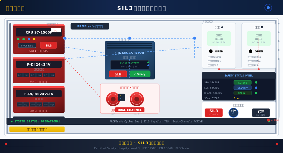
Overall System Architecture and Safety Integrity Level Allocation
The crane safety control system is designed in accordance with IEC 61508 and ISO 13849 (referenced from GB/T 16855.1-2012, "Safety of machinery — Safety-related parts of control systems"), targeting Safety Integrity Level (SIL) 3, corresponding to a probability of dangerous failure per hour below 10⁻⁷. The architecture follows a strict separation between the independent safety layer and the standard control layer: the standard control layer uses an S7-1500 CPU (e.g., 1513-1 PN) to execute motion control logic, while the safety layer runs on an S7-1500F safety CPU (e.g., 1515F-2 PN or 1517F-3 PN/DP) operating independently. Both layers coexist on the same PROFINET network via the PROFIsafe protocol.
| Safety Integrity Level (SIL) | Hazards per Hourprobability of failurePFH | Safety Availability | Application Scenarios |
|---|---|---|---|
| SIL1 | ≥10⁻⁶~<10⁻⁵ | 90%~99% | Simplifiedoverhead craneWarning Function |
| SIL2 | ≥10⁻⁷~<10⁻⁶ | 99%~99.9% | Medium-Light Dutyoverhead cranespeedLimitation |
| SIL3 | ≥10⁻⁸~<10⁻⁷ | 99.9%~99.99% | SIL3Yesoverhead cranesafety controlStandardGrade |
| SIL4 | ≥10⁻⁹~<10⁻⁸ | ≥99.99% | Nuclear WasteLifting and transport,Military |
The hardware architecture of the safety control system consists of three layers. The detection layer includes F-DI fail-safe digital input modules (collecting signals from Emergency Stop Buttons, Limit switches, safety door locks, and Overspeed Switches) and F-AI safety analog input modules (collecting signals from safety Encoders and Load Sensors). The control layer uses an S7-1500F safety CPU to run the safety program, with safety logic programmed in F-LAD or F-SCL and validated using the Safety Admin tool in TIA Portal. The actuation layer uses F-DQ safety digital output modules to drive Safety Relays, Brake Solenoids, and the STO terminals of Frequency Inverters (VFDs). The F-DQ modules feature built-in dual-channel disconnection, ensuring that a single fault cannot lead to the loss of a safety function.
F-CPU Selection and PROFIsafe Communication
The S7-1500F series safety CPUs integrate an F-runtime safety execution environment on top of the standard CPU. The F-runtime operates as an independent execution layer sharing the same CPU as the standard user program. The safety program is written in F-LAD and compiled into certified safety code using the Safety Admin tool in TIA Portal. Kelude selects different F-CPU models for overhead crane projects based on tonnage and safety function complexity: the CPU 1515F-2 PN (with 128KB program memory and 256KB safety F-memory) is used for standard cranes in the 20~50t range; the CPU 1517F-3 PN/DP (512KB program memory, supports distributed safety I/O) is chosen for heavy-duty cranes above 50t or applications requiring expanded safety functions; and the CPU 1511F-1 PN (48KB program memory, integrated safety I/O, deployed in compact Control Cabinets) is used for safety upgrades on simpler cranes.
The PROFIsafe communication protocol forms the basis for SIL3 safety data transmission. PROFIsafe adds an F-host and F-device safety layer on top of standard PROFINET RT communication. Safety data is exchanged via PROFIsafe telegrams between the F-host (safety CPU) and F-devices (F-DI/F-DQ modules, VFD safety functions). Each PROFIsafe telegram contains 2 bytes of safety data and 1 byte of CRC checksum (16-bit CRC + 8-bit CRC). The communication frame embeds a continuous watchdog counter (F_WD_Time default 150ms) and connection identifiers (F_Source_Add/F_Dest_Add), ensuring data integrity, timeliness, and correctness. PROFIsafe telegrams are transmitted in parallel with standard PROFINET telegrams within the IO cycle, without impacting the real-time performance of motion control. The safety data refresh rate matches the IO cycle, typically 4~8ms.
Configuring PROFIsafe in TIA Portal involves establishing an F-connection between the F-CPU and F-DI/F-DQ modules in the device view, setting the F_Source_Add and F_Dest_Add parameters (range 1~65534) for the F-parameter module, and configuring the F monitoring time F_WD_Time and the F_iPar_CRC check version number. The safety program is compiled and verified through simulation using the Safety Administration editor and testing functions in TIA Portal. The F-runtime automatically generates a 16-bit CRC identifier for each safety block; any code modification results in a CRC change, triggering re-validation of the safety subroutine.
Dual-Channel Emergency Stop Circuit and Safety I/O Redundancy
The emergency stop circuit in the overhead crane control system employs a dual-channel redundancy design. The two channels are completely independent both electrically and logically, and either channel can independentlyCut-off the power supply. Channel A uses an F-DI 16×24V DC module to capture the normally closed contact signals from the Emergency Stop Buttons (SB1~SB4). The safety CPU performs a dual-channel comparison in the safety program—the signal states of Channel A and Channel B must match within 500ms, otherwise an F-Diff fault is triggered and the system enters a stop state. Channel B directly connects the auxiliary contacts of the Emergency Stop Buttons in series via I/O wiring, which are then connected to the coil control circuit of the main contactor KM1 through the force-guided contacts of Safety Relay K1. This dual-channel design meets the SIL3 system requirements of IEC 61508—a single point of failure will not result in the loss of a safety function.
The selection of safety I/O modules follows the fail-safe principle—in the event of any single component failure within the module, the output must automatically switch to a safe state (i.e., open/de-energized). Each input channel of the F-DI 16×24V DC module has two independent test pulse generators built-in, outputting two test pulses with opposite phases to the Sensor/button terminals. By reading back these pulses, the module can detect line shorts and ground faults. The output channels of the F-DQ 8×24V DC/2A module integrate a dual-channel disconnect function internally—each output is controlled by two independent switches in series, so a fault in either switch can disconnect the load supply. The test pulse frequency for safety output signals is 1Hz (i.e., 500ms high level + 500ms low level test). The F-CPU refreshes the F-DQ output status synchronously within each safety scan cycle (20ms).
The placement of Emergency Stop Buttons follows the principles of the ISO 13850 standard for machinery safety—emergency stop design. Each overhead crane is equipped with an Emergency Stop Button in the operator's cab, on the floor remote control, on the maintenance platform, and on both End Carriages. All Emergency Stop Buttons are red mushroom-head type (diameter ≥30mm) and are set against a yellow background on the panel. Limit switches use positive opening contact mechanisms to ensure the safety circuit can be interrupted even if contacts are welded. The terminal limit switches and deceleration limit switches are installed independently and do not share a mounting bracket.
Dual Brake Redundancy Control and Load Slipping Prevention
The braking system of the overhead crane Hoisting mechanism is the core actuating component for safety control. In its SIL3 safety architecture, Kelude equips each crane with two independent Disc Brakes (Brake A and Brake B). Each brake consists of an independent electromagnet and pad assembly. Both brakes share a common Brake wheel hub but are mechanically installed completely independently. During normal operation, both brakes open and close simultaneously. If one brake fails, the other can still independently perform the braking function, meeting the single-fault tolerance capability required for SIL3.
The control sequence of the dual brakes is critical for preventing Load slipping. Opening sequence: The safety CPU sends opening commands to both Brake A and Brake B simultaneously via the F-DQ module—F-DQ channel 1 drives the electromagnet MK1 of Brake A, and channel 2 drives the electromagnet MK2 of Brake B. After MK1 and MK2 are energized, both brake pads release simultaneously. The release confirmation signal is detected by magnetic Proximity Switches SQ1 (Brake A) and SQ2 (Brake B) and sent back to the safety CPU via the F-DI module. Only after confirming that both brakes are fully open does the VFD receive the run enable signal. Closing sequence: After the motor speed is reduced to zero, the safety CPU issues the closing command—channels 1 and 2 of the F-DQ module are de-energized simultaneously. When MK1 and MK2 lose power, the brake pads are pressed against the Brake wheel hub by spring force. After confirming the brakes are fully closed, the safety CPU maintains the zero-speed state for 300ms before releasing the VFD enable.
Brake synchronization detection mechanism: The safety CPU records the switching time difference Δt between MK1 and MK2 (from command issuance to Proximity Switch state change) during each lifting cycle. When Δt exceeds the set synchronization threshold (default 50ms), the system records a synchronization deviation event. If deviations exceed the threshold for 3 consecutive cycles, or a single deviation exceeds 100ms, the safety CPU triggers an F-Diff alarm—the PLC immediately stops operation and enables STO. The Operation Panel displays the "Brake Unsynchronized" fault code, and the system can only be reset after maintenance personnel inspect the electromagnet supply voltage and pad wear condition. Regarding brake wear compensation, the system accumulates the opening time t_open and closing time t_close for each Brake application. These values are compared against the initial nominal values (t_open≈150ms, t_close≈100ms), and the lead time of the opening command is automatically adjusted based on the pad wear trend. This ensures that the actual opening timing and Braking torque remain within the safe range. Parameter self-tuning is performed automatically after a compensation cycle of 2000 operations.
Kelude Heavy Industry: Overhead & Gantry Crane Solutions
Kelude Heavy Industry specializes in the design and manufacture of heavy-duty overhead cranes, gantry cranes, and electric hoists. Our product line covers a full range of material handling equipment, from single-girder and double-girder bridge cranes to versatile gantry systems and explosion-proof hoists. We provide tailored solutions for workshops, warehouses, and industrial facilities across the United States and Europe.
5. Safety Functions: STO, SLS, SBC, and SDI
The four core safety functions of the crane safety control system are implemented through the coordinated operation of the S7-1500F safety CPU and the G120 VFD via the PROFIsafe interface. All safety functions are programmed in F-LAD and validated using TIA Portal Safety Admin. Each safety function block incorporates dual-channel signal processing, cross-comparison logic, and fail-safe output circuitry.
Safe Torque Off (STO) serves as the foundational safety function of the crane safety control system, corresponding to the STO sub-function defined in IEC 61800-5-2. STO directly cuts the pulse-enable signal to the G120 VFD via PROFIsafe, preventing the motor from generating unintended driving torque, with a response time of less than 20 ms. Trigger conditions include: activation of the Emergency Stop Button in the operator's cab, emergency stop command from the floor remote control, over-travel of any limit switch, opening of the safety door lock, abnormal feedback from the dual brakes, or a self-diagnostic fault in the safety CPU. Once STO is triggered, the VFD automatically applies internal braking (DC injection braking), allowing the overhead crane to coast to a stop under inertia and load. To reset STO, maintenance personnel must press the Reset button on the Operation Panel; the safety CPU verifies that all trigger conditions have been cleared and both brakes are fully engaged before re-enabling operation.
Safely Limited Speed (SLS) monitors motor speed in real time using a safety encoder (an incremental encoder whose pulse signals are read via F-DI, or a dedicated safety speed sensor providing direct feedback). When the trolley or crane bridge approaches an end limit switch at rated speed, within 200 mm of the limit position, the safety CPU sends a speed limit command (10% of rated speed) to the VFD via PROFIsafe. The VFD automatically executes deceleration, while the safety CPU continuously verifies that the actual speed remains within the defined safe range (≤0.3 m/s). If the safety CPU detects that the actual speed exceeds the SLS threshold (the safety PLC performs a speed comparison: actual speed n_act > SLS threshold n_sls for more than 50 ms), it immediately triggers an SLS-Fault and executes STO. The response time of the SLS function is less than 50 ms.
Safe Brake Control (SBC) works in conjunction with the dual brake redundancy control described earlier. The SBC function is executed by the F-SBR function block within the safety CPU. The F-SBR block outputs two independent SBC_Open commands to the F-DQ modules, which separately control the electromagnets of Brake A and Brake B. The safety CPU performs an SBC status check during every safety scan cycle: when STO is activated, SLS is triggered, or the safety CPU detects a zero-speed hold timeout in the VFD, the F-SBR automatically forces both brakes to close. Once both brakes are confirmed fully engaged, a "brakes closed" confirmation signal is sent to the VFD via PROFIsafe. SBC also includes a braking torque monitoring function, which infers whether sufficient braking torque is available by evaluating the Load Sensor signal and the motor's zero-speed state after brake closure. If the braking torque falls below 80% of the rated capacity, an SBC warning is triggered.
Safe Direction Indication (SDI) prevents the overhead crane from moving in an unintended direction before a reverse command is issued to the trolley or crane travel mechanism. SDI determines the actual direction of movement by analyzing the phase relationship of the safety encoder pulses and compares it against the direction feedback from the VFD. If the safety CPU detects that the actual direction of movement contradicts the control command direction for more than 100 ms, it triggers an SDI-Fault and executes STO. SDI direction conflicts are typically caused by incorrect VFD parameter configuration (such as reversed phase sequence in the motor cable) or encoder wiring errors. After an STO is triggered, maintenance personnel must inspect the wiring and parameters and then perform a manual reset.
| safety function | IECStandard | Response time | trigger condition | reset method |
|---|---|---|---|---|
| STO | IEC 61800-5-2 | <20ms | emergency stop/Overtravel/Safety Gate/Fault | ManualReset |
| SLS | IEC 61800-5-2 | <50ms | Approachlimit switchEnd(200mm) | Auto Release |
| SBC | IEC 61800-5-2 | <130ms | STOTrigger/Zero-Speed Hold Timeout | Automatic+Manual |
| SDI | IEC 61800-5-2 | <100ms | Direction Mismatch with Command | ManualReset |
6. Commissioning, Verification, and Safety Certification Process
Commissioning and verification of the crane safety control system follows a standardized six-step procedure. Step one involves safety function parameter configuration: create the safety program (F-LAD) in the TIA Portal Safety Editor, and configure the PROFIsafe connection parameters for the F-CPU and F-DI/F-DQ modules, including F_Source_Add (F-CPU address), F_Dest_Add (F-module address), F_WD_Time (default 150ms), F_iPar_CRC version check, and F_Param_CRC. Each safety function block is configured with dual-channel variables, with cross-comparison logic automatically generated by the F-runtime. After compilation, the F-prog CRC and F-CRC signatures are obtained; a mismatch between the two indicates the safety program has been modified and requires re-verification.
Step two is offline simulation verification. Load the safety program using PLCSIM Advanced, connect virtual F-DI/F-DQ modules, and simulate three fault scenarios through the PLCSIM Safety Simulation function: emergency stop activation, limit switch over-travel, and brake feedback failure. The simulation environment verifies STO response time (≤20ms), SLS speed threshold triggering accuracy (≤5%), SBC dual-brake synchronization deviation monitoring (50ms threshold triggering F-Diff alarm), and SDI direction conflict detection (100ms threshold triggering STO). Once all safety functions pass simulation, a Safety Validation Report is generated.
Step three covers on-site wiring verification. Use a multimeter and oscilloscope to verify point-by-point the test pulses of the F-DI module (1Hz square wave, 24V amplitude) and the dual-channel disconnection function of the F-DQ module. Measure the dual-channel wiring of the emergency stop button separately: the F-DI terminal pulse waveform on channel A and the hard-wired auxiliary contact continuity on channel B, confirming that both channels properly interrupt the safety circuit when the emergency stop button is pressed. The measured supply voltage to the brake electromagnet must fall within 22.8–24.5V, and the oscilloscope captures the electromagnet energizing current curve (peak approximately 1.6A, steady-state holding current approximately 0.8A).
Step four is load functional testing. Perform three trigger tests under both no-load and rated-load conditions: operator's cab emergency stop button, remote control emergency stop, and limit switch over-travel. Each trigger must verify correct execution of all safety functions—STO, SLS, SBC, and SDI. After STO is triggered, the VFD pulse enable must be disconnected within 20ms, and the Drive-CLiQ status changes to Fault. After SLS is triggered, the speed curve deceleration slope must match the VFD deceleration parameters, with maximum overshoot ≤10%. After SBC is triggered, both brakes must close simultaneously with Δt ≤50ms. SDI direction conflict is simulated by reversing the encoder A/B phase to verify triggering. All test data is recorded in the commissioning report.
Step five is TÜV certification preparation. Compile all safety-related documentation: system architecture manual (describing the functional division and interfaces between the safety layer and standard control layer), safety function definition table (quantifying trigger conditions, response times, and reset methods for STO/SLS/SBC/SDI), FMEA analysis table (listing all foreseeable single points of failure and their impact on safety functions), PROFIsafe connection parameter configuration table, and simulation verification report. All documentation is prepared in accordance with EN ISO 13849-1 and IEC 62061 format requirements.
Step six covers ongoing monitoring and periodic inspection. Once the safety control system is in operation, the safety CPU automatically logs safety events (emergency stop activations, SLS activations, brake desynchronization events, and F-Diff fault counts), generates a safety operating status summary every 24 hours, and pushes it to the central control room safety management platform via OPC UA. On-site maintenance personnel perform a comprehensive safety function test every quarter (in accordance with the safety-related clauses of ISO 4301 Crane Design Standard), and a third-party inspection body (such as TÜV or a national special equipment inspection institute) conducts an on-site safety function verification every 12 months. Test records are retained until the next inspection interval.
