

Overhead Crane PLC Control: S7-1500 Motion & Safety Logic
Overhead Crane PLC Control System Architecture: S7-1500 Motion Control and Safety Logic in Practice. The PLC control system is the operational brain of an overhead crane—a well-designed system must balance functional completeness, real-time responsiveness, and safety protection. This article focuses on the Siemens S7-1500 platform, detailing the engineering practices behind control architecture design, motion control programming, and safety logic implementation.
The PLC control system is the central nervous system of an overhead crane's automated operation. Downward, it drives VFDs and sensors via PROFINET IO; upward, it connects to the dispatching system and MES platform through OPC UA—while independently running SIL3 safety logic to protect both equipment and personnel. A well-designed PLC control system must strike the right balance between real-time performance, reliability, safety, and maintainability. Drawing on years of system integration experience with Siemens S7-1500 PLCs, Kelude has developed a standardized crane control architecture covering hardware selection, motion control function blocks, brake application timing, safety logic, and commissioning procedures. This article provides a detailed walkthrough of this engineering framework at the system architecture level.
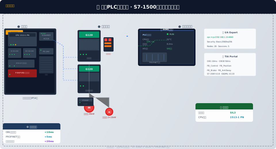
Hardware Platform Selection and System Configuration
The crane PLC control system is built around the Siemens S7-1500 series, with the specific CPU model determined by crane capacity and control complexity. For light-duty cranes under 20 tons, the CPU 1511-1 PN is used—it integrates 48 KB of program memory and 32 KB of data memory, sufficient for single-VFD drives with basic I/O control. Medium-duty cranes in the 20-to-50-ton range are equipped with the CPU 1513-1 PN, which offers 128 KB of program memory, supports multi-axis motion control and OPC UA server functionality, and is the most widely deployed model in Kelude's standardized crane projects. For heavy-duty cranes above 50 tons, the CPU 1516-3 PN/DP is specified, supporting three or more axes of motion control, multi-protocol communication, and more complex safety logic.
| CPUModel | applicable tonnage | Program Memory | Features |
|---|---|---|---|
| 1511-1 PN | ≤20t | 48KB | Single Variable Frequency Drive (VFD)+Basic IO |
| 1513-1 PN | 20~50t | 128KB | Multi-Axis+OPC UA |
| 1516-3 PN/DP | ≥50t | 256KB | Three-Axis+Multi-Protocol |
| 1515F-2 PN | 20~50t | 128KB | SIL3Safety-Rated |
For applications requiring SIL3 functional safety, the F-series safety CPUs (e.g., CPU 1515F-2 PN or CPU 1517F-3 PN/DP) are the recommended choice. These integrate standard and safety control within a single CPU via the PROFIsafe protocol, eliminating the need for a separate safety PLC and reducing both hardware cost and wiring complexity.
On the expansion module side, each overhead crane comes standard with one DI 32×24V DC digital input module (for limit switches, pushbuttons, and pendant controls), one DO 32×24V DC/0.5A digital output module (driving contactors, indicator lamps, and buzzers), and two AI 8×U/I analog input modules (for load sensors, laser distance measurement, and temperature signals). For safety-related I/O, F-DI 16×24V DC and F-DQ 8×24V DC/2A fail-safe modules are deployed. On the drive side, two G120 CU250S-2 DP control units with PROFINET interfaces are supplied as standard—one driving the hoisting motor and the other handling the crane bridge and trolley motors.
The system network topology is built on PROFINET RT industrial Ethernet, meeting the hard real-time requirement of a control-cycle time below 10 ms. The PLC acts as the PROFINET IO controller, while the G120 VFDs, ET200SP remote I/O stations, and encoder interface modules function as IO devices. All equipment is interconnected through industrial-grade network switches (Siemens SCALANCE XC216 or equivalent) in an MRP ring topology, with a ring-recovery time of under 200 ms.
TIA Portal Project Structure and OB Organization Block Assignment
Kelude adopts a standardized program structure for the crane PLC within the TIA Portal environment. The main cycle OB1 handles motion control, logic evaluation, and communication data exchange, with a cycle time of 10 ms to match the VFD speed-loop refresh rate. Cyclic interrupt OB30 (set at 50 ms intervals) executes position closed-loop and anti-sway algorithm updates, while OB32 (200 ms interval) handles status acquisition and fault diagnosis.
Startup OB100 performs system initialization, including clearing the fault buffer, verifying encoder zero-point positions, and resetting the emergency-stop state. Time-of-day interrupt OB10 runs once every 24 hours to accumulate operating hours and evaluate maintenance intervals. Hardware interrupt OB40 responds to the high-speed encoder Z-pulse zero-calibration signal.
Main Control Function Block
Position Closed Loop
Anti-Sway Control
Brake Application Control
Safety Logic
Fault Diagnosis
Motion Control Function Block Design
The core motion control logic of the overhead crane control system is encapsulated in two function blocks: FB_Control and FB_Position. FB_Control uses a finite state machine design with six states: IDLE (standby, waiting for task), ACCEL (S-curve acceleration to target speed), CRUISE (maintaining target speed), DECEL (S-curve deceleration to approach target position), POSITION (precision positioning at low speed to target position ±3mm), and STOP (brake application and VFD enable disconnection).
S-curve acceleration control is implemented through a five-segment speed profile within FB_Control: the initial acceleration segment OA ramps the jerk linearly from zero to its maximum, the hold segment AB accelerates at constant acceleration, and the transition segment BC ramps the jerk back to zero, entering constant-speed operation. The deceleration phase is a mirror image. Default jerk is 0.5m/s³ and maximum acceleration is 0.3m/s², keeping the crane bridge start impact coefficient beloww 1.1 (compared to 1.5–1.8 for conventional two-step start-stop).
For position closed-loop control, FB_Position fuses signals from three position sources: incremental encoder position (100Hz update, 0.1mm resolution), laser distance measurement absolute position (50Hz update, ±1mm accuracy), and Gray-code calibration points. A complementary filter (cutoff frequency 0.5Hz) blends the laser absolute positioning at low speed with the encoder incremental positioning at high speed, outputting an optimized fused position estimate. The position loop PI parameters are calibrated during commissioning via the TIA Portal Trace function: proportional gain Kp=8.0, integral time Ti=200ms.
Brake Control Timing and Anti-Slip Protection
Brake control on the hoisting mechanism is critical to both safety and equipment service life — the timing of brake release and application determines whether the suspended load is at risk of load slipping. Kelude has designed a five-stage brake control sequence implemented over PROFIsafe communication between the G120 VFD and the S7-1500 PLC.
The release sequence has three stages: Stage 1 — the PLC sends a "pre-excitation" command to the G120 via PROFIsafe, and the VFD builds up the motor excitation current (300ms duration); Stage 2 — the VFD establishes hoisting torque (110% of target torque), and the torque confirmation signal is sent back to the PLC over PROFIsafe (200ms duration); Stage 3 — once torque build-up is confirmed, the PLC outputs the brake release command, the brake electromagnet is energized (150ms response time), and after the brake is fully open, the PLC sends the "enable run" command.
The application sequence has two stages: Stage 1 — the PLC sends a "stop" command, and the VFD decelerates to zero speed using the deceleration ramp (zero-speed hold time 200ms); Stage 2 — the PLC sends the brake application command, the brake closes mechanically (100ms response time), and the VFD is de-energized after confirming zero speed. The total brake control cycle (from stop command to full brake application) does not exceed 850ms.
| Stage | Action | Sequence | Communication |
|---|---|---|---|
| Pre-Excitation | G120Flux Establishment Current | 300ms | PROFIsafe |
| Torque Build-Up | Torque Reached110%Acknowledgment Feedback | 200ms | PROFIsafe |
| Brake open | Electromagnetic Coil Energized+Brake Release | 150ms | DOOutput |
| Deceleration Stop | Decelerate to Zero+Zero-Speed Hold | 200ms | PROFIsafe |
| Brake close | Electromagnetic Coil De-Energized+G120Disable | 100ms | DO+PROFIsafe |
For brake lining wear compensation, the system records the actual opening time from the "brake open command" to the "brake magnet engaged feedback" during each brake application cycle. This measured value is compared against the initial nominal value (150ms), and the brake open command is progressively advanced based on friction lining wear, ensuring the actual opening point remains consistently within the target range.
Safety Logic Design and SIL3 Implementation
The safety functions of the overhead crane control system comply with IEC 61508 and ISO 13849-1, targeting Safety Integrity Level 3 (SIL3). Safety functions are implemented via the S7-1500F safety CPU and PROFIsafe communication protocol, with safety-related I/O connected through F-DI and F-DQ modules.
Key safety functions include: Safe Torque Off (STO) — when the Emergency Stop Button or a Limit switch is triggered, the VFD pulse enable is cut off directly via PROFIsafe with a Response time under 20ms; Safe Limited Speed (SLS) — the crane decelerates to 10% of rated speed 200mm before reaching the end limit, with a Response time under 50ms; Safety Brake Control (SBC) — the brake is automatically applied when STO is triggered to prevent Load slipping; Safe Direction Indication (SDI) — prevents the bridge travel mechanism and trolley mechanism from moving in the wrong direction before a reverse command is received.
The emergency stop circuit uses a dual channel redundant design: Channel A acquires the normally closed contacts of the Emergency Stop Button through the F-DI module, while Channel B connects the auxiliary contacts of the Emergency Stop Button via hardwired series wiring directly into the main contactor coil control circuit. Either channel can independently cut off the power supply when the emergency stop is triggered. The safety I/O test pulse frequency is 1Hz, and the PLC executes the safety logic written in F-LAD and refreshes the safety outputs within each safety scan cycle (20ms).
Commissioning Procedure and Parameter Tuning
The commissioning of the overhead crane PLC Control System follows six standard steps. Step one — network configuration and diagnosis: use PRONETA software to scan all devices on the PROFINET network, verify that device names and IP addresses match the TIA Portal project configuration, and confirm that all I/O devices are online.
Step two — VFD parameter configuration: download the G120 parameter set using STARTER or Startdrive software. For the Hoisting mechanism: P1300=20 (sensorless Vector Control), P1120=2.0s (acceleration time), P1121=2.0s (deceleration time), P1240=3 (Vdc_max controller activated). For the bridge travel mechanism: P1120=4.0s, P1121=4.0s.
Step three — static motor data identification: execute P1910=1 (static identification) and set to 1 (full identification). The identification process automatically measures motor parameters including stator resistance, rotor resistance, leakage inductance, and mutual inductance. The motor must not be connected to any mechanical load during identification.
Step four — position Calibration: use the TIA Portal control panel to manually run the crane to both end limit positions, record the deviation between Encoder and Laser Distance Measurement count values, and set the Encoder zero offset and positive/negative limit values.
Step five — brake timing verification: verify the torque build-up timing for brake opening and the zero-speed holding timing for brake closing under both no-load and rated load conditions. Use the Trace function to capture torque and speed curves, confirming that the brake timing parameters meet the five-stage control requirements.
Step six — OPC UA communication verification: use UA Expert to connect to the overhead crane PLC's OPC UA server, read the data types and value ranges of each node, verify the addresses and access permissions of the 26 published data nodes, and confirm that the dispatching system and MES platform can read and write normally.
