

Crane Buffer Selection Guide: 6 Types, Test Methods & Energy Ratings
Standard at a Glance
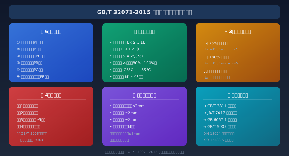
GB/T 32071-2015 "Buffers for Cranes" specifies the classification, technical requirements, test methods, and inspection rules for end-of-travel buffers used on crane travel mechanisms. It applies to bridge cranes, gantry cranes, portal cranes, and other types of lifting equipment. The standard classifies buffers into six types — hydraulic (PH), spring (PT), polyurethane (PU), rubber (PR), gas-hydraulic (PG), and polyester elastomer (PE) — and defines the design requirements for rated buffer capacity and buffer force, providing a unified technical basis for crane buffer selection and acceptance.
GB/T 32071 Scope and Development Background
Buffers are critical safety components on crane travel mechanisms. Mounted at both ends of the crane bridge and trolley travel rails, they absorb the kinetic energy generated when a crane or trolley over-travels due to a fault condition, protecting the metal structure and drive system from impact damage. Per the GB/T 3811 Crane Design Standard, all crane travel mechanisms must be equipped with buffers and end stops at both rail ends, with buffer capacity sized to absorb the impact energy under the most severe operating condition.
GB/T 32071-2015 was developed under the technical jurisdiction of the National Technical Committee for Standardization of Lifting Appliances (SAC/TC 227) and officially released in 2015. The standard draws on international references including DIN 15024 (buffer dimensions and design principles) and ISO 12488-5 (tolerance requirements for bridge and gantry cranes), combined with actual operating conditions and field experience in China. It covers buffer selection for cranes ranging from 0.5t to over 500t lifting capacity.
The core technical content of the standard covers: structural configurations and designations for the six buffer types, design requirements for rated buffer capacity and buffer force, material and manufacturing process requirements, four type test methods, and factory inspection and type inspection rules. Because buffer failure can lead to severe accidents such as crane derailment, end carriage deformation, or even complete overturning, GB/T 32071 is typically applied in conjunction with GB 6067.1 Safety Code for Lifting Appliances, together forming a complete technical framework for crane end-of-travel protection.
Six Buffer Types: Construction and Working Principles Compared
GB/T 32071 classifies buffers into six types based on their energy absorption mechanism. Each type has distinct application ranges and performance characteristics, and selection must consider the crane service rating, travel speed, and available mounting space.
① Hydraulic buffer (PH type): Absorbs impact energy through the damping force generated as hydraulic oil is forced through an orifice. Buffer efficiency reaches 90%–95%, making it suitable for heavy-capacity bridge cranes in A5 to A8 duty classes. Advantages include constant buffer force and minimal rebound; disadvantages include structural complexity, high seal quality requirements, and the potential for oil leakage over extended service.
② Spring buffer (PT type): Stores impact energy through elastic deformation of a helical spring. Simple, reliable, and low-cost, it is widely used on small- and medium-capacity cranes (≤50t). However, spring buffers exhibit a rebound effect with a rebound rate of approximately 10%–15%, so additional travel clearance must beReserved in the design and installation.
③ Polyurethane buffer (PU type): Absorbs impact energy through viscoelastic deformation of polyurethane elastomer. Lightweight, corrosion-resistant, and maintenance-free, it has seen growing adoption in A3 to A6 duty bridge cranes in recent years. Buffer efficiency is approximately 75%–85%, but performance degrades noticeably at high temperatures (above 70°C).
④ Rubber buffer (PR type): Made primarily from natural or synthetic rubber, it offers the simplest construction and lowest cost, suited to A1 to A4 light-duty, low-speed small cranes. Buffer stroke is relatively short (typically ≤100mm) with an efficiency of about 60%–70%, appropriate for small lifting equipment up to 20t capacity.
⑤ Gas-hydraulic buffer (PG type): Combines gas compression energy storage with hydraulic damping, achieving high energy absorption with minimal rebound. Efficiency exceeds 95%, making it ideal for extra-large gantry cranes and ladle cranes with lifting capacity ≥100t. Although more expensive, it is insensitive to variations in impact velocity and performs well in complex operating conditions.
⑥ Polyester elastomer buffer (PE type): Made from thermoplastic polyester elastomer (TPEE), combining rubber-like elasticity with plastic strength. Excellent fatigue resistance (cycle life ≥500,000 cycles) and a buffer efficiency of 80%–88% give it a clear advantage in automated warehouse stackers and frequent start-stop applications.
Kelude Heavy Industry uses a modular buffer configuration on its bridge cranes: PU polyurethane buffers come as standard, with an upgrade path to PH hydraulic or PG gas-hydraulic buffers for metallurgical and heavy-duty applications, meeting a wide range of customer requirements.
Buffer Selection: Rated Capacity Requirements and Energy Calculation
The two core selection parameters for a buffer are rated buffer capacity Ek and rated buffer force Fe. Per Section 5.2 of GB/T 32071, the rated buffer capacity must satisfy Ek ≥ 1.1Emax, where Emax is the maximum impact energy the buffer must absorb under the most severe operating condition. The 1.1 safety factor covers energy deviations introduced by rail slope, wind load, and manufacturing tolerances.
Impact energy E is calculated at three levels. Level 1 is the normal impact energy E₁ at 75% rated travel speed — the kinetic energy generated when the crane, under rated load, strikes the buffer at 75% of its rated speed. Level 2 is the maximum impact energy E₂ at 100% rated speed — the extreme-case energy when the crane hits the buffer at full speed after a limit switch failure and the operator fails to brake in time.
Level 3 is the extreme impact energy E₃ after drive system deceleration. For VFD-controlled cranes, even if the limit switch fails, the Electrical Control System typically provides multi-stage deceleration protection, so the actual impact velocity may be well below rated travel speed. In this case, E₃ can be calculated based on the reduced impact velocity, but E₂ must still be used as the energy basis for buffer selection in the design.
Buffer force Fmax is another critical parameter, equal to the maximum reaction force the buffer exerts on the crane structure during impact. Per GB/T 3811 Section 9.6, the maximum buffer force must not exceed 1.25 times the allowable load-bearing capacity of the connected structural member (end carriage or rail end stop), ensuring the buffer absorbs impact energy without causing secondary damage to the crane structure. This requirement is particularly important when retrofitting buffers on existing runway beams in older factory buildings, where the beam connection capacity must be verified simultaneously.
Buffer Installation Accuracy and End Stop Coordination Requirements
Installation accuracy directly affects buffer impact energy absorption and service life. Section 6.2 of GB/T 32071 specifies three key dimensional requirements — center height difference, horizontal skew, and vertical skew — coordinated with the technical conditions of JB/T 7017 Buffers for Cranes. The center height deviation between buffers on opposite sides of the crane rail must be controlled within ±2mm, horizontal skew must not exceed ±2mm, and vertical skew is likewise limited to ±2mm.
Misalignment between the buffer and the end stop is a common installation issue. The standard requires that the center of the buffer impact face and the center of the end stop impact face be aligned within 3mm. If the alignment deviation exceeds this limit, the buffer will be subjected to eccentric loading, causing localized stress concentration and accelerating fatigue failure of the buffer element (spring, polyurethane block, etc.). In severe cases, this can lead to weld cracking at the buffer mounting base.
Additionally, for bridge cranes with large spans (L≥25m), the main girder deflects noticeably under full load (limited to L/800 per GB/T 3811), creating a height difference at the end carriage buffer impact center between no-load and full-load conditions. It is recommended to align the buffer based on the full-load impact center during installation, or to provide ±2mm of vertical adjustment allowance on the mounting base using the "half-load center" principle.
Kelude Heavy Industry performs laser measurement and documentation of buffer installation accuracy on every bridge crane before shipment, and each crane is delivered with a buffer installation accuracy inspection report. During the crane selection design phase, the Kelude technical team can recommend matching buffer types and specifications based on actual factory building span, lifting capacity, and duty classification, ensuring both rated buffer capacity and installation accuracy fully comply with GB/T 32071.
Four Type Tests and Factory Inspection Acceptance Criteria
Chapter 7 of GB/T 32071 specifies the type test items and methods for buffers, covering four core tests. Newly designed or significantly modified buffer products must pass all four type tests before entering mass production. Each test has clear acceptance criteria and data recording requirements, and a Type Test Report must be issued and archived after completion.
① Static characteristic test: The buffer is progressively loaded on a universal testing machine or hydraulic Test Bench while the force-displacement curve (F-S curve) is recorded to verify that the elastic stiffness characteristics fall within the design tolerance range. For hydraulic and gas-hydraulic buffers, the orifice flow-pressure characteristic curve is also measured to confirm that the damping force-to-velocity relationship matches the design parameters.
② Buffer capacity verification test: Impact testing is conducted using either the Drop hammer impact method or the Pendulum impact method, with a specified impact energy of 1.1 times the rated buffer capacity. The peak buffer force, buffer stroke, and rebound distance are measured during impact. Acceptance criteria: peak buffer force must not exceed 1.1 times the rated buffer force, buffer stroke must be within ±5% of the nominal stroke, and rebound must not exceed 15% of the buffer stroke.
③ Durability test: The buffer is subjected to at least 50,000 cyclic loading tests at room temperature. The test frequency depends on the buffer type: 1–2 Hz for polyurethane and rubber types, and 0.5–1 Hz for spring and hydraulic types. After testing, the buffer elements are inspected for cracks, permanent deformation, or leakage, and the buffer capacity must not drop by more than 10% of its initial value. The durability test follows the general requirements of ISO 4306 — Crane test specifications and procedures.
④ Environmental adaptability test: This includes buffer performance testing under high temperature (+55°C), low temperature (−25°C), and damp-heat cycling (40°C/93% RH). After the high-temperature test, the buffer capacity must not drop by more than 15%. No brittle cracking or sticking is allowed after the low-temperature test, and metal parts must show no significant corrosion after the damp-heat test (corroded area ≤ 5%).
Buffer Type Parameter Comparison: 6 Key Configurations
| Type Code | Buffer efficiency | Rebound rate | Applicable to Lifting Capacity | Applicable to Work Duty / Classification | Reference Life(Number of Cycles) |
|---|---|---|---|---|---|
| PH Hydraulic Type | 90%~95% | ≤5% | 10t~500t | A5~A8 | ≥200,000 Cycles | PT Spring Type | 80%~88% | 10%~15% | 2t~50t | A3~A7 | ≥100,000 Cycles |
| PU Polyurethane Type | 75%~85% | 8%~12% | 1t~80t | A3~A6 | ≥150,000 Cycles |
| PR Rubber Type | 60%~70% | 15%~20% | 0.5t~20t | A1~A4 | ≥50,000 Cycles |
| PG Gas-Hydraulic Type | ≥95% | ≤3% | 50t~500t+ | A6~A8 | ≥300,000 Cycles |
| PE Polyester Elasticity Body Type | 80%~88% | 5%~8% | 1t~63t | A4~A7 | ≥500,000 Cycles |
Buffer Inspection Items and Corresponding Standard Clauses
| Inspection Item | Inspection Type | Reference Standard Clause | Acceptance Criteria | Inspection Cycle |
|---|---|---|---|---|
| Visual and Dimensional Inspection | Factory Acceptance Test | GB/T 32071 §6.1 | None Crack/Corrosion/Deformation | Per Unit |
| installation accuracy Detection | Factory Acceptance Test | GB/T 32071 §6.2 | Center Height Difference≤±2mm | Per Unit |
| Static characteristic test | Type Test | GB/T 32071 §7.3 | F-SCurve Deviation≤±5% | New Design/Per5Year |
| Buffer Capacity Verification | Type Test | GB/T 32071 §7.4 | Fmax≤1.1Fe, STolerance±5% | New Design/Per5Year |
| Durability test | Type Test | GB/T 32071 §7.5 | ≥50,000 Cycles, Capacity Reduction≤10% | New Design/Per5Year |
| Environmental adaptability test | Type Test | GB/T 32071 §7.6 | High/Low Temperature Thermal Cycling Compliance | New Design/Per5Year |
6 Key Technical Data Points for Buffer Selection
≥1.1
Rated buffer capacity factor
Ek ≥ 1.1Emax
≤15%
Maximum allowable rebound rate
As a percentage of buffer stroke
95%
Highest buffer efficiency for gas-hydraulic type
PG-type design ceiling
±2mm
Mounting center height tolerance
Horizontal/vertical misalignment
≥50000
Minimum durability test cycles
Type test requirement
6
Standard buffer classifications
PH/PT/PU/PR/PG/PE
Further Reading
GB 6067.5 Safety Regulations for Bridge and Gantry Cranes — Covers mandatory safety design requirements for end stops and buffers, applied in conjunction with JB/T 7017.
Understanding GB/T 28264 Safety Monitoring and Management System for Lifting Appliances — Learn how travel limiters interlock with buffers in safety monitoring configurations to enable automatic deceleration before impact.
GB/T 5972 Wire Rope Maintenance, Inspection and Discard Criteria for Cranes — A key reference for wear parts management; buffers likewise require periodic inspection and preventive replacement.
Frequently Asked Questions
Q: What is the practical difference between hydraulic and spring buffers in real-world service?
A: Hydraulic buffers deliver a buffer efficiency of 90%–95%, maintain constant buffer force throughout the stroke, and keep rebound rate at ≤5%, making them suitable for heavy-duty large-capacity cranes (10t–500t) in A5~A8 duty classes. Spring buffers have a simpler construction but exhibit a higher rebound rate of 10%–15% and a buffer efficiency of 80%–88%, and are typically used on small-to-medium cranes rated ≤50t. For selection, hydraulic buffers are recommended for heavy-duty metallurgical and ladle cranes, polyurethane (PU) buffers for general purpose bridge cranes, and spring (PT) buffers for light-duty workshop cranes.
Q: What specific durability test requirements does GB/T 32071 impose on buffers?
A: Clause 7.5 of GB/T 32071 specifies a minimum of 50,000 test cycles for buffer durability testing. The test frequency depends on buffer type: 1–2 Hz for polyurethane and rubber types, and 0.5–1 Hz for spring and hydraulic types. Acceptance criteria require that the buffer capacity after testing does not drop by more than 10% of its initial value, and that buffer elements show no cracks, permanent deformation, or fluid leakage. For PE polyester elastomer buffers, the actual service life can exceed 500,000 cycles thanks to superior material fatigue characteristics.
Q: What should be done when a crane buffer develops abnormal noise or oil leakage during operation?
A: First, stop the crane immediately and inspect the buffer's external condition and mounting tightness. For hydraulic buffers with oil leakage, check whether seals are aged or damaged; seal rings should be replaced preventively every 2 years (per JB/T 7017, Clause 8.3). For spring buffers with abnormal noise, the likely causes are wear between the spring end coils and the seat ring, or excessive guide sleeve clearance. Measure the guide clearance (standard requirement: ≤0.5mm); if exceeded, replace the guide sleeve or the entire buffer assembly. Kelude recommends establishing a monthly buffer inspection log to record external condition, mounting bolt torque, and buffer stroke data, and to develop a preventive replacement schedule based on usage frequency.
Q: What is the required mounting center height tolerance for buffers on a 50-ton bridge crane?
A: Clause 6.2 of GB/T 32071 explicitly requires that, regardless of crane capacity, the center height difference between buffers at both ends of the same rail be controlled within ±2mm, with horizontal and vertical misalignment also limited to ±2mm. For a 50-ton bridge crane, since full-load deflection of the main girder can reach L/800 (approximately 31mm for a 25m span), buffer installation should use the impact center under full-load conditions as the shaft alignment reference, or provide vertical adjustment shims on the mounting base to ensure alignment deviation stays within ≤3mm at full load. This requirement also applies to medium-to-large bridge cranes with lifting capacities from 32t to 80t.
Related Articles
GB/T 3811-2008 Crane Design Standard: 9 Load Combinations and Work Duty Selection from M5 to M6 — The core design standard for cranes, covering load combinations and work duty requirements for buffer selection.
Understanding GB/T 28264 Safety Monitoring and Management System for Lifting Appliances — Key requirements for safety monitoring configurations that integrate travel limit switches with buffer protection.
GB 6067.5 Safety Procedure for Bridge and Gantry Cranes — Mandatory safety design requirements for end stops and buffers, used in conjunction with GB/T 32071.
JB/T 7017-2015 Buffers for Cranes — Standard Interpretation — Industry standard covering buffer technical specifications and installation requirements, forming a complete technical framework with GB/T 32071.
