

Crane Automation Retrofit: 4 Steps to Unmanned Operation
📋 Key Summary
Automation retrofitting is not merely swapping a frequency inverter or deploying an unmanned overhead crane. Kelude Heavy Industry breaks down the automation of European-standard double-girder cranes (50t–300t) into four layers: variable frequency speed control, safety perception, remote collaboration, and unmanned decision-making. Implementation typically proceeds in phases: 7–15 days per single machine and 30–60 days for workshop-level integration. Load monitoring accuracy reaches ±2%, positioning accuracy achieves ±10mm, and anti-swing angles are controlled within ±0.2°. These four layers are stacked progressively without dismantling existing mechanical structures; specific scopes remain subject to the actual contract.
Layer 1: Variable Frequency Drive Upgrade & Speed Control Parameters
Many users mistakenly equate automation retrofitting with "swapping a VFD and adding a remote control." However, when retrofitting 50t–300t European-standard double-girder cranes, Kelude Heavy Industry targets the entire speed chain rather than isolated components. This includes operational signals, VFD output, motor characteristics, braking units, and encoder feedback. For cranes originally using contactor-based resistor cutting for speed control, we remove the resistor-cutting panel and replace it with a crane-specific Vector VFD. For models already using variable frequency but lacking sufficient speed performance, we focus on recalibrating acceleration/deceleration times, low-frequency torque, and braking resistor matching.
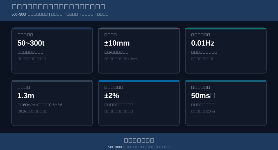
This layer directly determines inching/jog mode, load slipping prevention, and low-speed positioning. Taking Kelude’s 50t European-standard double-girder crane as an example: after VFD installation, the hoisting mechanism achieves stepless speed regulation from 0.5 to 5 m/min (rated speed was 5 m/min); Long Travel Speed ranges from 20 to 60 m/min; and Cross Travel Speed ranges from 10 to 40 m/min. The VFD offers an output frequency resolution of 0.01Hz and a current loop response cycle of 2ms. On large-tonnage 300t models, the hoisting mechanism typically employs dual-motor rigid synchronization, keeping speed deviation within ±0.5% to prevent main girder torsion caused by unsynchronized double lifting points.
Braking safety must be recalculated rigorously. According to FEM 1.001 Crane Design Specification, the braking distance and brake safety factor requirements dictate that braking at design speed should not rely solely on mechanical brakes. Instead, electrical deceleration should engage first, followed by mechanical brake application. Consider this engineering calculation: With a Long Travel Speed of 60 m/min (1 m/s) and an electrical braking deceleration of 0.5 m/s², the theoretical braking distance is s = v²/(2a) = 1²/(2×0.5) = 1m. If the safety monitoring Response time is 0.3s, the vehicle coasts 0.3m during this interval. Therefore, the anti-collision safety distance should be set to 1m + 0.3m = 1.3m. This 1.3m is not an arbitrary figure but a verifiable boundary value for site calculations.
Braking resistor matching also falls under Layer 1. For an 80t European-standard double-girder hoisting mechanism equipped with a 75kW motor, peak power during lowering is estimated at 1.1–1.2 times the motor power, approximately 82.5kW–90kW. Resistance values must be calculated based on the VFD's DC bus voltage and braking current. Actual selection remains subject to the actual contract, avoiding fixed-resistance assumptions. Insufficient resistor heat dissipation can cause DC bus voltage spikes during continuous lowering, leading to overvoltage faults.
Upon delivering Layer 1, Kelude Heavy Industry provides equipment parameter tables, VFD parameter configurations, braking distance recalculation reports, and interlock logic checklists, rather than simply installing a VFD and leaving.
Layer 2: Safety Monitoring & Status Perception
Layer 2 transforms "human observation and judgment" into "sensor acquisition, PLC processing, and system shutdown." TSG 51-2023 Crane Safety Technical Supervision Regulation imposes more systematic requirements on lifting appliances regarding safety monitoring, Capacity limitation, travel protection, and wind/sliding resistance. Many existing cranes only have mechanical limit switches and Overcurrent Protection; retrofitting requires adding load sensors, height encoders, bridge/trolley position detection, anemometers, motor winding temperature sensors, and vibration sensors at critical points.
Kelude Heavy Industry utilizes the following sensing layer parameters: Load monitoring accuracy ±2%; height measurement Resolution 5mm; bridge/trolley position refresh cycle 20ms; motor bearing temperature alarm threshold 85°C; winding temperature alarm threshold 135°C. Upon reaching an alarm threshold, a three-tier strategy is triggered: Level 1 sends remote alerts, Level 2 initiates automatic deceleration, and Level 3 executes a stop-and-brake sequence. These levels are independently judged rather than consolidated into a single program block.
Avoid relying on single-point ultrasonic or laser detection for anti-collision. Consider two 50t double-girder cranes in the same bay traveling at 60 m/min (1 m/s). Based on the previously calculated braking distance of 1m plus a 0.3m safety response buffer, the triggering distance for stopping should be no less than 1.3m. However, the triggering distance for deceleration is recommended at 3m. This reduces the Long Travel Speed from 60 m/min to 10 m/min before entering the stop zone, preventing heavy loads from swinging due to abrupt high-speed braking. Refer to Kelude’s guide on anti-collision safety distance for related logic.
Structural health monitoring is essential, not optional. Weld cracks in the main girder expand under heavy loads over time. Kelude recommends flaw detection on critical weld seams during retrofitting, with optional acoustic emission or strain gauges for long-term trend analysis. Single-point values are less meaningful than trends. See weld crack detection for specific test methods.
The essence of this layer is not adding a "black box," but integrating all signals into a unified PLC to create a traceable, stop-capable control circuit involving capacity, speed, temperature, position, and electronic fence status. Without this layer, remote operation and unmanned operation lack a safety foundation.
Layer 3: Remote Operation & Multi-Crane Collaborative Scheduling
Remote operation does not mean moving the operator cab to the ground floor or simply adding an Industrial Remote Control. Layer 3 focuses on Positioning Accuracy, communication latency, task allocation, and multi-crane interlocks. Ground stations or centralized control rooms must view real-time position, load, limit status, and task status for each overhead crane; the signal link must have no significant breakpoints or delays.
For position detection, bridge and trolley systems often use Laser Distance Measurement or Gray-code bus positioning systems. Bridge Positioning Accuracy can reach ±10mm, trolley ±10mm, and Hook height ±5mm. Communication uses industrial wireless networks, keeping link latency under 50ms and control command cycles at 20ms. If communication jitter exceeds 80ms, the "feel" of remote operation degrades significantly, making automatic grab/release inadvisable.
During multi-crane coordination, Kelude integrates electronic fences and PLC interlocks into a single logic set: When two cranes in the same bay are less than 3m apart, both reduce speed to 10 m/min. At distances under 1.3m, they trigger a stop and lock reverse movement, requiring manual confirmation to resume. For cross-bay transitions, red zones are set at intermediate passages; one crane must clear the red zone before the other enters, preventing high-altitude collisions.
When interfacing with workshop MES or ERP systems, the task queue can cache 20 handling commands, supporting allocation via shortest path, earliest deadline, and minimum energy consumption. For example, if a 300t and a 100t crane share a bay, tasks under 50t with overlapping paths are prioritized for the 100t crane, reserving the 300t crane for heavy-load stations. Scheduling rules are dynamic, calculated based on station workload, load weight, and energy weights, rather than being static.
The typical bottleneck in this layer is rail straightness and communication reliability. If rail straightness deviates by more than 3mm per 10m, or if the height difference between side rails exceeds 5mm, the bridge will drift regardless of sensor precision, worsening repeat positioning. Therefore, Kelude verifies rails and wheels before retrofitting; non-compliant sections are repaired first. Software compensation cannot overcome physical limits.
| RetrofitHierarchy | PrimaryRetrofitObject | key parameters | TypicaldeliveryScenario | Kelude Heavy IndustryImplementation Boundary |
|---|---|---|---|---|
| Level 1Variable Frequency Drive (VFD)Upgrade | Motor、Frequency Inverter / VFD、braking unit、Encoder | 0.5~60m/minSteplessSpeed control、0.01HzResolution | Anti-Load slipping、Inching / Jog Mode、Low Speedprecise positioning | Retain Original Beam Structurestructure,recheckWheel loadAnd / Withbraking distance |
| Level 2 Safety Perception | Sensor、PLC、monitoring screen、temperatureMeasurement Point | ±2%Load、5mmHeight、85℃alarm | metallurgical、Yard、RegulationsUpgrade | According to《TSG (Special Equipment Safety Technical Regulation) 51 Safety Technical Specification for Special Equipment-2023 Crane Safety Technical Supervision Regulation lifting appliancessafety technical supervision regulation》recheck |
| Level 3collaborative scheduling | PositioningDevice、Industrial Wireless、Ground Station、MESinterface | ±10mmPositioning、50msInternal Link、20Task Cache Entries | Cross-aisle Operation、WorkshopLogistics | Prior torecheckrail straightnessHeight Difference Relative to Side Rails |
| Level 4 Unmanned Decision-Making | vision、anti-sway controlAlgorithm、vibrationDiagnosis、DualPLC | ±0.2°sway angle、25.6kHzSampling、200msShutdown | Lights-outproduction line、High-risk Materials、Repeattransporting | PhasedAcceptance,Single MachineTestingNot less than72Hours |
Level 4 Automation: Unmanned Operation and Adaptive Decision-Making
Level 4 builds upon the previous three tiers by integrating visual recognition, anti-sway control, path planning, and fault prediction. Unmanned operation does not mean the complete absence of human involvement; rather, it delegates repetitive lifting tasks to the system while reserving human intervention for exception handling. For European-standard double-girder cranes ranging from 50t to 300t, Kelude Heavy Industry typically implements a three-tier human-machine division of labor: automatic operation, monitoring with intervention, and manual takeover.
Visual recognition systems determine the position of the suspended load, the attitude of the lifting spreader, and detect personnel intrusion in the working area. Cameras positioned at a height of 15m can maintain an identification error within ±15mm, with continuous repeated positioning deviations not exceeding 10mm over 20 cycles. For different types of loads such as steel coils, aluminum coils, and ladles, the system employs specific gripping strategies and torque limits to prevent incorrect grasping or underloading.
Anti-sway control is the core of stability in unmanned operations. Kelude Heavy Industry utilizes feedforward velocity shaping combined with closed-loop sway angle compensation, limiting the lifting spreader’s swing amplitude to within ±0.2° and achieving static convergence in less than 5s. The algorithm divides acceleration changes for the crane bridge and trolley into multiple smooth curves rather than applying full speed abruptly. For detailed algorithmic strategies, see AI Anti-Sway Algorithm.
Regarding fault prediction, vibration sensors operate at a sampling rate of 25.6kHz, enabling envelope analysis of reducer bearing, gear meshing frequency, and early-stage motor bearing faults. If the energy of characteristic bearing frequencies rises continuously by more than 6dB for one hour, the system triggers a maintenance alert rather than waiting for a temperature alarm to shut down. Data from weld crack detection on the main girder is also archived long-term as an input for structural safety monitoring.
In terms of safety redundancy, unmanned overhead cranes employ dual PLC hot standby, cross-verification of dual encoder positions, and emergency stop circuits configured to SIL2 standards. Any single point of failure triggers a safe shutdown within 200ms. Kelude Heavy Industry decomposes each unmanned retrofit into five modules: mechanical structure recheck, electrical transmission, perception systems, control software, and acceptance testing. These are verified in stages, with single-machine testing lasting no less than 72 hours and workshop-level joint debugging lasting no less than 168 hours. Specific timelines are subject to the actual contract.
FAQ
Q: How long does it take to retrofit a 50t European Standard Double-Girder crane for unmanned operation?
A: Single-machine variable frequency drive (VFD) upgrades typically take 7–15 days; safety monitoring and remote pendant installation take 30–45 days; full-function unmanned operation takes 60–90 days. On-site confirmation based on mechanical wear, track accuracy, and interface conditions is required. Timelines are subject to the actual contract.
Q: Does automation retrofitting require replacing the main girder and end carriage?
A: No, provided the main girder’s stiffness, camber, and weld inspection results meet qualifications. Kelude Heavy Industry first verifies wheel load, fatigue status, and deflection. Local reinforcement is applied only if necessary; replacing girders is not the default approach.
Q: Can all manual labor be eliminated after unmanned retrofitting?
A: No. Unmanned systems handle repetitive transporting, but human operators are still required for exception handling, lifting irregular materials, and confirming safety pins. Personnel roles shift from direct operation to monitoring and intervention.
Q: What should be done if positioning accuracy cannot reach ±10mm after retrofitting?
A: First, verify rail straightness, crane skewing, and wheel diameter difference. If rail straightness exceeds 3mm per 10m or the height difference between side rails exceeds 5mm, track correction must precede control algorithm tuning. Software compensation alone has its limits.
