

Gantry Crane Girder Stiffness: Deflection Limits
📋 The Standards Governing Main Girder Static Stiffness
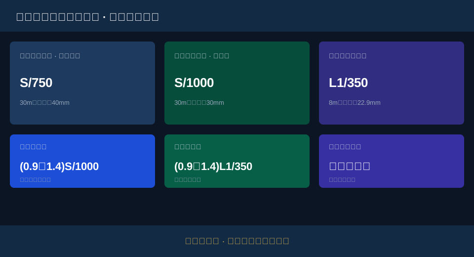
FEM 1.001 Crane Design Standard is the top-level basis for the entire machine design. The vertical static deflection at mid-span is governed by positioning accuracy: for moderate positioning accuracy with a simple speed control system, it must not exceed span divided by 750; for high positioning accuracy with a refined speed control system, it must not exceed span divided by 1,000.
GB/T 14406-2011 General-Purpose Gantry Crane specifies acceptance values for main girder camber and cantilever upwarp at the model level: for a newly installed gantry crane, main girder camber is 0.9‰–1.4‰ of the span, and cantilever upwarp is 0.9‰–1.4‰ of the effective cantilever length.
TSG 51-2023 Crane Safety Technical Supervision Regulation places main girder stiffness within the mandatory framework of supervision inspection and periodic inspection. Permanent deformation and measured deflection after the static load test are key criteria for pass/fail determination.
Which Standards Govern Gantry Crane Main Girder Stiffness
Main girder static stiffness is not dictated by any single standard. It is the result of four categories of standards—design, product, inspection, and testing—converging layer by layer. Only by clarifying this hierarchy can deflection limits be properly applied.
FEM 1.001 Crane Design Standard is the first layer of reference. It ties the vertical static deflection at mid-span to hoisting and positioning accuracy and the sophistication of the speed control system: for moderate positioning accuracy with a simple speed control system, the limit is span divided by 750; for high positioning accuracy with a refined speed control system, it tightens to span divided by 1,000. Behind this approach lies a counterintuitive logic—the old practice of determining stiffness by working class has given way to determining stiffness by positioning accuracy, because what drives the stiffness requirement is how precisely the crane must place a load, not how many lifts it performs per day.
GB/T 14406-2011 General-Purpose Gantry Crane supplements acceptance values for camber and upwarp at the model level. The design standard specifies what value to use; the product standard specifies what the girder should look like at factory delivery. Both address different stages of the same main girder.
TSG 51-2023 Crane Safety Technical Supervision Regulation places stiffness within the mandatory framework of supervision inspection and periodic inspection. Standards describe ideal conditions, but workshops are never ideal—main girders develop creep-induced deflection under long-term alternating loads, and the supervision regulation exists precisely to guard against this slow, insidious weakening. Kelude Heavy Industry translates the requirements of all four standard categories into a verifiable stiffness parameter table in its European Standard Double-Girder gantry crane solutions, so that acceptance is well-founded.
Converting Mid-Span and Cantilever Deflection Limits to Millimeters
Converting a ratio like span divided by 750 into millimeters is a routine field calculation—and an easy one to get wrong. The key is simply this: use the correct length basis for the denominator.
Mid-span deflection uses the main girder span as its basis. Take a 30 m span: the moderate-accuracy limit equals 30,000 mm divided by 750, which is 40 mm; the high-accuracy limit equals 30,000 mm divided by 1,000, which is 30 mm. The 10 mm difference between the two tiers corresponds to entirely different cross-section stiffness and steel consumption.
Cantilever deflection uses the effective cantilever length as its basis, not the overall span. Assuming an effective cantilever length of 8 m, the limit equals 8,000 mm divided by 350, which is approximately 22.9 mm. Intuition and experience fail here—some would apply the 30 m span to the cantilever and arrive at an erroneously large limit, thereby overlooking the very location that needs the tightest control.
Main girder camber is also calculated on the basis of span: a 30 m span corresponds to a camber between 27 mm and 42 mm. This range is not a tolerance—it is a design allowance. Camber provides elastic rebound space for deflection under full load, keeping the main girder slightly arched or nearly level at rated load. Most people stop here, but a deeper question remains: the camber value depends on which deflection tier the design follows, and the two must be matched. Kelude Heavy Industry lists span, effective cantilever length, deflection tier, and camber range together in its parameter table, so that field calculations stay consistent.
| Comparison Parameter | FEM 1.001 Crane Design Standard-2008 | GB/T 14406-2011 | TSG (Special Equipment Safety Technical Regulation) 51 Safety Technical Specification for Special Equipment-2023 Crane Safety Technical Supervision Regulation | ISO 4310 | FEM (Fédération Européenne de la Manutention) 9.321European Standard (EN) |
|---|---|---|---|---|---|
| StandardNature | design specification | Modelproduct standard | safety supervisionProcedure | test specification | design specification |
| mid-spanstatic deflection | S/750orS/1000 | Reference3811Value | InspectionJudgment Item | Load testMeasured | ItemSpecificationContractual Agreement |
| Cantilever endDeflection | L1/350 | Specified Limit | InspectionJudgment Item | Load testMeasured | ItemSpecificationContractual Agreement |
| camber | (0.9~1.4)S/1000 | (0.9~1.4)S/1000 | InspectionJudgment Item | TestAfter≥0.7S/1000 | ItemSpecificationContractual Agreement |
| CantileverUpward Camber | (0.9~1.4)L1/350 | (0.9~1.4)L1/350 | InspectionJudgment Item | TestAfter≥0.7L1/350 | ItemSpecificationContractual Agreement |
| Value-Oriented | Positioning Accuracy+Speed control | ModelAcceptance | safety baseline | Measured Judgment | limit state method |
| Hierarchy of Effect | Recommended National Standard | Recommended National Standard | Mandatory InspectionProcedure | Recommended National Standard | European Standard (EN)System |
Main Girder Deflection Limits: S/750 vs S/1000 for Medium and High Positioning Accuracy
Neither S/750 nor S/1000 is inherently more correct — the right choice depends entirely on the operating condition. Selecting the wrong tier means a costly mismatch between structural stiffness and investment.
S/750 applies to general-purpose operations with simple speed control and medium hoisting and positioning accuracy, such as routine loading and unloading in an open-air storage yard. Under full load, the main girder is permitted to deflect by span divided by 750 — for a 30 m span, that equals 40 mm.
S/1000 applies to operations equipped with a full-featured control system such as Variable Frequency Speed Control, where positioning accuracy requirements are high — for example, precision assembly or equipment installation alignment. These conditions demand a stiffer main girder under full load, tightening the limit to 30 mm for a 30 m span.
The theory holds, but three practical factors routinely undermine it:
① The operating condition is underestimated — actual hoisting accuracy requirements turn out higher than declared;
② The control system is downgraded after selection — the advanced speed control assumed at the design stage never materializes;
③ At large spans, S/1000 significantly increases the main girder cross-section and steel consumption.
Choosing a tier is not a matter of ticking a box on a drawing. Hoisting process, control system configuration, and investment budget must all be weighed together in a single decision matrix. FEM 9.321 — Main Girder Design Specification, as a European Standard (EN) for main girder design, also uses mid-span deflection as its core verification indicator, but applies the limit state method with different load combination factors. The allowable deflection for the same span may therefore differ from that under the Chinese standard. At Kelude Heavy Industry, custom projects begin by confirming the positioning accuracy requirements of the hoisting process with the end user, then working backward to determine whether S/750 or S/1000 is the right fit — rather than defaulting to a single value.
| Conflict Scenario | StandardArequirements | StandardBrequirements | Recommended Engineering Practice |
|---|---|---|---|
| CamberValue Range | design specification(0.9~1.4)S/1000 | TestAfter≥0.7S/1000 | Newly Installed Value0.9~1.4‰,TestShall Not Be Less Than After0.7‰ |
| DeflectionGrade | S/750MediumAccuracy | S/1000HighAccuracy | PerHoistingProcess andcontrol systemExplicitly Stipulated in Contract |
| CantileverDeflection | designL1/350 | TestMeasured Value | Newly Installed ValueL1/350As Upper Limit,Measured Not Exceeding |
| European Standard (EN)Coexist with National Standard | Recommended National StandardS/750~S/1000 | European Standard (EN)Per ItemSpecificationContract | DualStandardItem Value System Explicitly Stipulated in Contract |
Three Common Misconceptions: Mistaking Main Girder Deflection for Strength Verification
Deflection governs whether deformation exceeds allowable limits; strength governs whether the structure will fail. These are two entirely separate checks, yet they are frequently conflated. All three misconceptions stem from this confusion.
Misconception 1: Selecting deflection limits according to Work Duty. This practice dates back to the era of light, medium, and heavy classification. Current design specifications have shifted to selecting deflection thresholds based on positioning accuracy and speed control systems. Applying A5 or A6 to S/750 or S/1000 yields values that are both unfounded and potentially too lenient.
Misconception 2: Measuring only camber, not static deflection. Camber is the geometric profile under no-load conditions; static deflection is the elastic deformation under full load. The two are not interchangeable. A gantry crane with acceptable camber can still exceed static deflection limits — especially when the main girder cross-section has been downsized through non-standard modifications.
Misconception 3: Ignoring the independent limit for the cantilever end. The deflection limit for a gantry crane cantilever is the effective cantilever length divided by 350 — stricter than the mid-span limit. In the field, attention is often fixed on mid-span while the cantilever end has already deflected enough to affect trolley travel without anyone noticing.
What all three misconceptions share is treating "looks about right" as "meets the standard." Kelude Heavy Industry's Factory Acceptance Test measures and archives four data sets together — mid-span static deflection, cantilever deflection, camber, and permanent deformation after unloading — qualifying or rejecting based on data, not visual inspection.
📋 Positioning Accuracy Determines the Tier
Define lifting and positioning accuracy and speed control system first, then choose S/750 or S/1000
📋 Camber Acceptance
New installation camber 0.9–1.4‰S; after testing, no less than 0.7‰S
📋 Don't Skip the Cantilever
Effective cantilever deflection L1/350; upward camber 0.9–1.4‰L1
📋 Static Load Measurement
Dual criteria: full-load deflection and permanent deformation after unloading
📋 Dual-Standard Agreement
When European and Chinese standards coexist, specify the value system in the contract
📋 Permanent Deformation Red Line
Any permanent deflection exceeds the elastic range — automatic rejection
📖 Related reading: The main girder is a crane's backbone — structural design insights into imported vs. domestic European-standard double-girder cranes | How to convert between FEM and GB Work Duty classifications — the actual gap between European-standard and Chinese national standard cranes
FAQ
Q: How does the standard specify the vertical static deflection limit at mid-span of a gantry crane main girder?
A: FEM 1.001 (equivalent to FEM 1.001) takes a positioning-accuracy-driven approach. For moderate positioning accuracy with a simple speed control system, the vertical static deflection at mid-span shall not exceed span divided by 750. For high positioning accuracy requirements with a refined speed control system, it shall not exceed span divided by 1000. At a 30 m span, the two tiers correspond to 40 mm and 30 mm respectively. The cantilever end has a separate limit: effective cantilever length divided by 350.
Q: How do I choose between the span/750 and span/1000 deflection tiers?
A: The difference lies in positioning accuracy and the sophistication of the speed control system. For operating conditions with simple speed control and moderate positioning accuracy requirements, span/750 is sufficient. For applications requiring precise positioning with a refined control system such as Variable Frequency Speed Control, span/1000 applies. At Kelude Heavy Industry, during the customized solution phase, we write the applicable limit into the Technical Agreement based on the hoisting process and control system configuration.
Q: How many millimeters of deflection is allowed at mid-span for a gantry crane with a 30 m span?
A: At span/750, the allowable vertical static deflection at mid-span for a 30 m span is 40 mm. At the high-precision tier of span/1000, it is 30 mm. These are elastic deformation limits under full-load static conditions. No permanent deformation is permitted after unloading during the static load test.
Q: How do you tell whether a gantry crane's main girder deflection is out of spec?
A: During the static test with rated load, measure the deflection at mid-span relative to the two end supports and compare it against the limit of span divided by 750 or 1000. Also check for permanent deformation after the load is removed — any permanent deflection means the girder has gone beyond its elastic range. Kelude Heavy Industry runs a static load test to ISO 4310 before delivery and provides the measured data.
Kelude Heavy Industry specializes in high-end customization of European Standard double-girder cranes. Main girder stiffness, deflection limits, and camber values are verified unit by unit against each project's operating condition, and all key parameters are backed by verifiable factory data and acceptance documents. Final configuration is subject to the actual contract.
