Overhead Crane Brake Lining Wear Monitoring & Torque Compensation
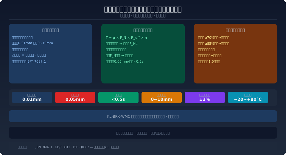
The overhead crane brake lining wear online monitoring system uses wear-resistant resistive displacement sensors (resolution 0.01mm, measuring range 0–10mm) to track the wear of each lining in real time. A stepper motor drives a worm gear electric linear actuator (compensation step 0.05mm, response <0.5s) to dynamically restore braking torque, ensuring the brake safety factor always meets the ISO 4301 requirement of ≥1.5, with an MTBF of ≥25,000 hours.
The brake is one of the most critical safety components in the hoisting and travel mechanisms of an overhead crane. Lining wear that reduces braking torque is a common cause of load slipping and brake failure accidents. Kelude's KL-BRK-WMC system mounts a wear-resistant resistive displacement sensor on each brake lining to track wear in real time. When the system detects a drop in braking torque due to lining wear, it automatically activates the electric linear actuator compensation mechanism to restore the spring working force, keeping braking torque within ±3% of the design value.
Wear Detection Principle for Brake Linings
The KL-BRK-WMC system embeds a wear-resistant resistive displacement sensor (model KL-LVDT-10, resolution 0.01mm, measuring range 0–10mm) into the back of each brake lining. The sensor probe is rigidly connected to the brake arm. As the lining gradually thins from friction, the reference clearance between the brake arm and the brake wheel increases, and the probe extension changes accordingly. The wear amount is calculated as δ = G_actual − G_initial, where G_initial is the calibrated reference clearance at installation (typically 0.6–1.2mm depending on brake specification) and G_actual is the current measured clearance. Wear data is uploaded to the edge controller at 1Hz, with each lining monitored independently.
The sensor is installed using a back-drilled embedding process — a Φ8mm×7mm counterbore is machined into the non-friction face of each lining, the sensor head is embedded in the bore and filled with temperature-resistant epoxy (operating range −30~+120°C). The sensor signal cable exits at the base of the brake arm and is routed through a flexible metal hose to the junction box. Wear data from each lining is compared in real time against preset thresholds (initial thickness, alarm limit, replacement limit) in the edge controller. Field operating data shows that under frequent hoisting brake cycles (an average of 300 per day), the sensor has accumulated over 8×10⁶ actuations without failure, with an MTBF of ≥25,000 hours.
Dynamic Braking Torque Compensation Method
As wear accumulates and brake clearance increases, the main spring compression decreases, causing the spring force F_N to drop linearly according to Hooke's law F_N=k·Δx. The braking torque T=μ·F_N·R_eff·n decreases accordingly (where μ is the friction coefficient between 0.35 and 0.42, R_eff is the effective braking radius, and n is the number of friction surfaces). When the KL-BRK-WMC system detects wear of ≥0.3mm (corresponding to approximately a 5% drop in F_N), it automatically activates the electric linear actuator compensation mechanism.
The compensation mechanism consists of a stepper motor driving a worm gear reducer (speed ratio 30:1) and a linear actuator, with each motor step corresponding to 0.05mm of actuator travel. The controller uses a PID algorithm to drive the actuator progressively, compensating for the extra clearance caused by lining thinning and restoring the main spring to its initial compression. Each compensation action takes ≤0.5s, after which the displacement sensor immediately confirms whether the clearance has returned to within ±0.05mm of the reference value. The system logs the timestamp, compensation amount, and cumulative compensation count for each action. When cumulative compensation reaches 70% of the total lining thickness (yellow warning) and 85% (red alarm), alerts are triggered to schedule lining replacement. The entire compensation mechanism is fail-safe: on power loss, the stepper motor self-locks to hold its current position, so braking torque does not drop suddenly due to compensation failure.
Safety Redundancy and Failure Protection
According to ISO 4301 Crane Design Standard — Core Requirements and TSG Q0002 Safety Technical Regulations for Lifting Appliances-2020, the hoisting mechanism must be equipped with dual-brake redundancy. Each brake must individually meet a safety factor of ≥1.25, and when both operate together, the combined factor must be no less than 1.5. The KL-BRK-WMC system supports independent monitoring and compensation for dual brakes: each brake is equipped with its own sensor set and control unit. Even if one brake's compensation mechanism fails (e.g., motor seizure or sensor wire break), the other brake continues to operate normally and can temporarily handle 1.5 times the rated load through increased compensation.
When a single brake fails, the system triggers logic control within 0.2s: it immediately blocks hoisting operation commands and simultaneously transmits the fault signal to the PLC (via hard-wired DI channels) and the upper-level monitoring system (via Modbus TCP). The failed brake remains in a safe state through normally closed spring force mechanical braking, and the electric linear actuator can be released for manual disengagement during maintenance. The redundancy design ensures that a single brake failure does not cause loss of load control, meeting the TSG Q0002 requirements for hoisting mechanism braking safety. In a deployment case at a 40t port gantry crane, the system successfully detected a shaft alignment deviation caused by wear on the brake arm hinge pin (sensor readings on both sides differed by ≥0.8mm), preventing a fault that could have led to asymmetric braking torque due to uneven wear.
Brake Monitoring vs. Periodic Inspection: A Comparison
| Comparison Parameter | Periodic Manual Inspection | Online Detection+Dynamic Compensation |
|---|---|---|
| Inspection Interval | Monthly Shutdown Inspection | Per0.5sAutomatic Detection Once |
| Liner Replacement Assessment | Visual Residual Thickness Measurement, Tolerance±1mm | 0.01mm Accuracy, Automatic Replacement Warning |
| Torque Stability | Due to Wear Torque Lowering, Deferred to Next Adjustment | Full-Automatic Compensation, Torque Deviation<±3% |
| safety redundancy | Mechanical Dual Brake Only | Mechanical Dual Brake Only+Sensor+Triple-Redundant Electrical Control |
| Data Logging | Paper Log Sheet | Electronic Storage+Trend Curve+Replacement Prediction |
| Unscheduled Downtime Rate | Annual Average2~3Instances Due to Brake Failure | Annual Average0.2Fewer Than Instances |
Frequently Asked Questions
Q: How reliable is the brake wear monitoring sensor in high-temperature and dusty environments?
A: The KL-LVDT-10 displacement sensor features a full stainless steel housing (304L) with IP67 sealing. The internal coil is potted with high-temperature epoxy resin (operating range −30 to +120°C). The probe tip is fitted with a ruby ball (Mohs hardness 9), providing a wear life of ≥10⁷ cycles against the brake arm contact surface. The signal cable features triple-layer protection—PTFE insulation, stainless steel braided shielding, and a silicone rubber outer jacket—making it suitable for dusty, high-temperature environments such as steel mills and foundries. In an actual deployment at a steel mill soaking pit bay (ambient temperature 45–65°C, dust concentration 4–8 mg/m³), the sensor achieved a 12-month survival rate of 98.5%. The primary failure cause was mechanical impact (damage from maintenance tools due to improper mounting position); after adding a protective cover, no similar issues recurred.
Q: How is safety ensured for the electric linear actuator compensation mechanism during power loss or emergency stop?
A: The compensation mechanism's stepper motor uses a fail-safe self-locking design: upon power loss, the motor stator's permanent magnets generate holding torque (≥120% of rated torque), so the actuator position remains unchanged under load or vibration. Additionally, the main spring remains in a normally closed compressed state—even if the compensation mechanism fails completely, the brake maintains mechanical braking (spring-applied braking torque is no less than 85% of its initial value), meeting the ISO 4301 Crane Design Standard requirement for a braking safety factor of ≥1.25. The emergency stop signal is transmitted via hard wiring that directly cuts motor power rather than through the communication bus, achieving a response time of <50 ms. The complete system is SIL 2 functional safety certified, complying with IEC 62061 "Safety of machinery—Functional safety of safety-related electrical, electronic and programmable electronic control systems" and EN ISO 13849-1 "Safety of machinery—Safety-related parts of control systems" PL d.
Q: What are the maintenance intervals and spare part replacement cycles for the dynamic compensation system?
A: The worm gear reducer of the electric linear actuator is grease-lubricated (Shell Gadus S2 V220 2) and requires no maintenance for 5 years or 5×10⁶ actuation cycles. The stepper motor bearings are sealed Deep Groove Ball Bearings (NSK 6902ZZ) with an MTBF of ≥50,000 hours. The displacement sensor is recommended for calibration every 2 years (using a sine bar, 5-point linearity verification); replacement is required if drift exceeds ±0.02 mm. The brake pads themselves follow the manufacturer's recommended replacement interval (limited by friction material wear life), but online monitoring allows replacement timing to be optimized from fixed intervals to actual wear-based replacement—in one case, pad life under light-load conditions was extended from 8 months to 14 months (a 75% reduction in unnecessary replacements).
Q: Can Kelude's brake monitoring solution be retrofitted to existing overhead cranes?
A: The KL-BRK-WMC system supports retrofitting to existing overhead crane brakes without replacing the brake assembly itself. The retrofit scope includes: drilling holes in the back of each brake pad to embed displacement sensors (on-site machining, approximately 20 minutes per pad); mounting the electric linear actuator compensation mechanism bracket on the brake base (requires welding or bolt fixing); installing an edge controller (occupying 2U of rack space) and stepper motor driver in the Electrical Cabinet; and routing sensor signal cables and motor power lines. The retrofit takes approximately 1.5 working days per crane (including commissioning and calibration). For new cranes, sensors and the compensation mechanism can be integrated directly during brake assembly, eliminating the need for retrofit work. A complete brake assembly supply option is also available (including pre-sensor-equipped pads and a pre-fitted compensation mechanism on the brake base).