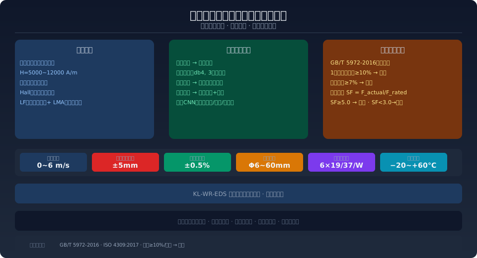
Crane Wire Rope Electromagnetic Detection & Broken Wire Localization

Electromagnetic in-line inspection of overhead crane wire ropes uses strong magnetic field excitation (H=5000~12000A/m) and a 16-channel Hall Effect Sensor array to detect broken wires (positioning accuracy ±5mm), cross-sectional area loss (detection accuracy ±0.5%), and corrosion defects in real time. Combined with the GB/T 5972-2016 discard criteria, the system enables live residual strength assessment, with a CNN classification accuracy of 94.7%.

The wire rope is a critical load-bearing component of the overhead crane hoisting mechanism. Its condition directly affects equipment safety and personnel protection, as governed by the discard requirements of GB/T 5972-2016 Cranes — Wire Ropes — Care and Maintenance, Inspection and Discard and the safety factor provisions of ISO 4301 Crane Design Standard. Traditional manual visual inspection and caliper measurement suffer from significant blind spots, slow inspection speeds, and an inability to quantify internal damage. The KL-WR-EDS wire rope electromagnetic inspection system employs strong magnetic field excitation combined with a high-sensitivity Hall Effect Sensor array, enabling continuous inspection at normal crane travel speeds (0~6 m/s). A single pass covers the full rope length, achieving broken-wire positioning accuracy of ±5 mm and cross-sectional area loss detection accuracy of ±0.5%.


System architecture diagram


How Electromagnetic Wire Rope Inspection Works

The KL-WR-EDS system operates on the principle of electromagnetic induction: the inspection probe forms a closed magnetic circuit with the excitation coil and the wire rope under test. The excitation current generates a near-saturation axial magnetic field (field strength H=5000~12000 A/m) inside the rope. When broken wires, corrosion, or wear are present, the magnetic permeability changes abruptly at the defect location, causing magnetic flux lines to leak from the rope surface at the defect edges. The 16 Hall Effect Sensors (sensitivity 5mV/mT) arranged circumferentially on the inner wall of the probe detect these leakage flux signals, which are then processed through differential amplification and 24-bit AD conversion before being sent to the edge processing unit.

Sensor signals fall into two categories: the LF (Local Flaw) channel captures flux leakage pulse signals generated by broken wires and pitting corrosion, with pulse amplitude correlating to the number of broken wires and gap width; the LMA (Loss of Metallic Area) channel measures longitudinal changes in the rope's metallic cross-section using the magnetic flux integration method to calculate the sectional area loss rate. The LF channel samples at 20 kHz and the LMA channel at 1 kHz, with synchronized acquisition ensuring precise correlation of broken-wire positions. The probe features a split/clamshell design that allows installation and removal without detaching the rope end, with a setup time of approximately 5 minutes.


Signal Processing and Broken Wire Localization Algorithm

Raw sensor signals are first preprocessed by hardware band-pass filters (LF channel: 0.1 Hz~2 kHz; LMA channel: DC~100 Hz), then fed into a digital signal processing pipeline:

Stage 1 — Three-level decomposition denoising using the db4 wavelet basis, with a soft-threshold method to eliminate background noise from inter-strand friction;

Stage 2 — Pulse peak detection on the LF channel, with the peak threshold set at 5 times the standard deviation of background noise; signals below this threshold are treated as noise and ignored;

Stage 3 — Spatial correlation across adjacent sensor channels (16 Hall Effect Sensors evenly distributed around the circumference) to reject single-channel interference. A valid broken-wire event is confirmed only when two or more adjacent channels simultaneously detect a pulse with an amplitude ratio greater than 2:1.

Broken-wire positioning accuracy is jointly determined by inspection speed and sampling rate. At the rated speed of 2 m/s, the 20 kHz sampling rate yields a spatial resolution of 0.1 mm per sample point. Combined with the Hall sensor spacing (22.5° circumferential distribution) and probe length (240 mm), the final axial positioning error for broken wires is ≤±5 mm. Broken-wire counting uses a CNN classification model (MobileNetV2 lightweight architecture), with input as an 8×128 LF-LMA dual-channel time-frequency spectrogram and output as the number of broken wires (0~12 wires per lay length) and defect type (broken wire / corrosion / wear / indentation). The model was trained on 1,200 sets of laboratory calibration data, achieving a classification accuracy of 94.7%. The system automatically generates a wire rope health report that pinpoints the exact location of each broken wire (distance in meters from the rope end), the number of broken wires, and the associated risk level.

Inspection Speed
0~6 m/s
Broken Wire Positioning
±5 mm
Sectional Area Loss
±0.5%
Rope Diameter Range
Φ6~60 mm
Hall Channels
16-channel
Accuracy
94.7%

Residual Strength Assessment and Discard Criteria

Based on measured broken wire counts and cross-sectional area loss, the system evaluates residual strength in accordance with GB/T 5972-2016 Specification for Inspection and Scrapping of Wire Ropes for Cranes and the ISO 4309 Wire Rope Inspection Standard (ISO 4309:2017, Cranes — Wire ropes — Care, maintenance, inspection and discard). The assessment model first calculates the effective metallic cross-sectional area ratio R = A_actual / A_nominal, then applies a strength reduction coefficient adjusted for the distribution pattern of broken wires. When the number of broken wires within a single rope lay reaches 10% of the total wire count, the system directly flags the rope as discard-level (red alarm). For conditions below the discard threshold, the system issues tiered warnings across three levels.

The warning levels are as follows:

Blue Notice — Cross-sectional area loss of 3–5% or 1–3 broken wires per lay; shorten inspection interval to monthly.

Yellow Warning — Cross-sectional area loss of 5–7% or 4–7 broken wires per lay; schedule replacement within 2 weeks.

Red Alarm — Cross-sectional area loss of ≥7% or ≥10% broken wires per lay; stop operation and replace immediately.

The residual strength safety factor is defined as SF = F_actual / F_rated. For new ropes, SF ≥ 6.0 is required (per M5 work duty classification); for ropes in service, SF ≥ 4.0 is considered acceptable, and SF < 3.0 triggers removal from service. In one case, a 32t overhead crane wire rope (6×36WS-IWRC, Φ22mm) at a steel mill was inspected using the KL-WR-EDS system, which detected 6 broken wires concentrated within a single lay at 3.2m from the fixing point (LMA loss of 6.8%). The yellow warning prompted timely replacement, preventing a potential rope failure.


Comparison with Traditional Inspection Methods

Comparison ParameterManual Visual Inspection+CaliperElectromagnetic In-situ Detection
Detection Speed0.1~0.3 m/s (Manual Step-by-Step)0~6 m/s (No-Deceleration Normal Operation)
Internal Damage DetectionNon-Visible(Surface Wire Breaks Only)Internal Wire Breaks, Corrosion, and Wear All Detectable
Quantitative AccuracyVisual EstimationWire Break Count±1Count, Cross-Sectional Area±0.5%
Detection Coverage RateSampling10~20%Rope Length100%Full-Length Continuous Coverage
Data TraceabilityPaper RecordsElectronic Records+Trend Curves+Automated Reporting
Operator DependencyReliance on Technician ExperienceAIAutomatic Assessment, Operator Only Requires Operator Training

Frequently Asked Questions

Q: What are the wire rope diameter and construction limitations for electromagnetic inspection of crane wire ropes?

A: The KL-WR-EDS sensor is available in three size ranges — Φ6~22mm, Φ18~40mm, and Φ36~60mm — covering the standard wire rope diameters commonly used on overhead cranes. The rope must be made of ferromagnetic material (either steel core or fiber core is acceptable); stainless steel wire ropes cannot be inspected with this system due to their low magnetic permeability. Common rope constructions including 6×19, 6×36, 6×37, and 8×19 have been calibrated and verified. For multi-strand constructions (e.g., 35×7) and compacted ropes, detection sensitivity is slightly reduced (approximately 10–15%), which can be recovered through model fine-tuning. For shaped-strand ropes (triangular or oval strand), the irregular inter-strand gaps increase the complexity of the magnetic flux leakage signal, and the broken-wire counting error increases from ±1 wire to ±2 wires.

Q: How is the inspection sensor mounted on the wire rope, and what impact does it have on normal crane operation?

A: The sensor features a split-body hinged design — two half-shells are secured with stainless steel latches, and the inner surface is lined with polyurethane guide rollers (Shore A 85 hardness) with a wear life of ≥5,000 km against the wire rope. The sensor is connected to a fixed point on the crane trolley frame via a flexible load-bearing cable, allowing it to freely follow the rope's lateral movement. Under normal hoisting mechanism operation, the installed sensor imposes no additional friction on the wire rope (guide roller rolling friction coefficient <0.05) and has no effect on lifting speed or braking performance. The recommended installation position is between the drum exit and the fixed pulley, where the rope's straight section is longest and lateral deflection is minimal. Installation or removal takes one person approximately 5 minutes and does not require taking the crane out of service.

Q: How consistent are the electromagnetic inspection results with the discard criteria of ISO 4309?

A: In 65 comparative tests (including manual visual inspection, MT magnetic particle inspection, and destructive verification), the broken-wire count from electromagnetic inspection showed a correlation coefficient of R²=0.93 against the destructive verification results, with a 98.5% agreement rate on whether the discard threshold was reached. The only discrepancy occurred in a case of severe corrosion where multiple broken wires had fused together — the electromagnetic inspection counted 11 broken wires per lay length (indicating discard), while physical dismantling revealed 9 broken wires plus 2 half-broken wires. The system tends toward conservative judgments, which aligns with the safety-first principle. The cross-sectional area loss measurement showed a mean deviation of 0.3% and a maximum deviation of 1.2% compared to the weighing method. The system automatically compares its results against manual re-inspection data on a quarterly basis; if the deviation exceeds 2%, a recalibration is triggered.

Q: How does Kelude's electromagnetic wire rope inspection solution compare to imported brands (e.g., LMA+LF systems)?

A: The Kelude KL-WR-EDS system matches international first-tier brands (such as INTROS from Russia and WDI from Germany) on core technical specifications, with three key differentiators. First, the split-body sensor design is better suited to the confined installation spaces typical of overhead cranes — imported thread-through sensors require removing the rope end, with installation taking approximately 2 hours. Second, the built-in CNN classification model can distinguish between three defect types — broken wires, corrosion, and mechanical wear — whereas imported systems only report raw LMA+LF signals that require manual interpretation. Third, the system supports 4G remote data transmission and cloud platform trend analysis, while imported solutions typically offer only local storage with USB data export. In terms of pricing, a complete KL-WR-EDS system costs approximately 55–65% of an equivalent imported solution and includes a 3-year warranty plus remote calibration services.

Related News

contact

contact us

phone:
+86 13903802779

mail:3915269@qq.com

Working hours: Monday to Friday

Wechat
Wechat
SHARE
TOP