

Explosion-Proof Crane Solutions for Chemical & Dusty Areas
Explosion-proof crane design must first establish the hazardous area classification of the operating environment. Hazardous zones are defined in accordance with the GB 3836 series and the IEC 60079 framework, using a combined protection approach that incorporates Flameproof (Ex d), Increased Safety (Ex e), and Intrinsic Safety (Ex ib) methods.
Hazardous Area Classification for Explosion-Proof Cranes
In chemical, petrochemical, and pharmaceutical facilities, the presence of explosive atmospheres imposes stringent requirements on lifting equipment. Determining the hazardous area classification of the operating environment is the first and most critical step in selecting and designing an explosion-proof crane. Under the GB 3836 series and the IEC 60079 framework, explosive zones are categorized according to the frequency and duration of flammable gas or vapor presence.
| Explosion-proof Zone | Definition | Typical Locations | Explosion Protection Class Requirements |
|---|---|---|---|
| 0Zone | Explosive gas atmosphere present continuously or for long periods | Inside storage tanks, Inside reactors, Inside piping | Ex ia(Intrinsically safe)or special Certification Equipment |
| 1Zone | Explosive gas atmosphere likely to occur in normal operation | Chemical industry Workshop Filling opening, Near sampling points, Pump room | Ex d(Flameproof), Ex ib, Ex px |
| 2Zone | Unlikely to occur in normal operation, If it occurs, persists for a short period only | Periphery of storage tanks, Well-ventilated production area Workshop | Ex d, Ex e, Ex n |
The classification of hazardous areas is fundamentally based on the probability of an explosive atmosphere occurring. Zone 0 represents the most stringent environment, requiring intrinsically safe (Ex ia) equipment that ensures insufficient energy to cause ignition under any fault condition. Zone 1 is the most common high-risk area in the chemical industry, where cranes typically employ flameproof (Ex d) designs. Zone 2 presents a relatively lower risk, allowing for Increased Safety (Ex e) or non-sparking (Ex n) equipment, which reduces equipment costs while maintaining safety.
Actual area classification requires comprehensive consideration of ventilation conditions, release source grades, gas density, and other factors. Per GB 50058-2014 (Code for Design of Electrical Installations in Explosive Atmospheres), a certified safety assessment organization must issue a hazardous area classification drawing defining zone boundaries and ratings before crane selection proceeds. Kelude strictly follows this process in explosion-proof crane projects, ensuring every unit precisely matches the operating conditions.
Additionally, combustible dust environments are classified under GB 12476.1-2013 into Zones 20, 21, and 22, corresponding to dust that is continuously present, likely to occur in normal operation, and occurs occasionally for short periods, respectively. Dust explosion protection differs technically from gas explosion protection, as detailed in subsequent sections.
Explosion-Proof Crane Classifications: Ex d, Ex e, and Ex ib Explained
The classification of an explosion-proof crane directly determines its safety assurance capability in hazardous environments. Per the GB 3836 series standards, explosion-proof cranes primarily employ the following protection types: Flameproof (Ex d), Increased Safety (Ex e), and Intrinsic Safety (Ex ib). Understanding the technical implications of these types is fundamental to proper selection and design.
Flameproof (Ex d) is the most widely used type for explosion-proof cranes. Its core principle involves housing electrical components that may produce sparks or arcs within a rugged enclosure capable of withstanding the pressure of an internal explosion and preventing flame propagation to the surrounding atmosphere. Ex d enclosure design must comply with the strict requirements of GB 3836.2-2010, including: enclosure material (typically cast steel or stainless steel), joint width (flange gap width of at least 6 mm), joint gap (not exceeding 0.1 mm for Zone 0), and pressure testing (hydrostatic test at 1.5 times the reference pressure or an explosion test). On cranes, Ex d is primarily applied to critical electrical components such as motors, control boxes, and junction boxes.
Increased Safety (Ex e) adopts a different design philosophy from Flameproof. Rather than containing an explosion, it prevents the occurrence of sparks, arcs, or hazardous temperatures at the source by enhancing the reliability of electrical connections, reducing temperature rise, and improving the protection rating (minimum IP54). Ex e requirements include: insulation materials with a higher thermal class (at least Class F); anti-loosening structures for conductor connections; creepage distances and clearances increased by more than 30% over standard equipment; and rated operating temperatures not exceeding allowable limits. Ex e is typically suitable for Zone 2 environments and is restricted to non-moving parts that do not produce sparks under normal operation.
Intrinsic Safety (Ex ib and Ex ia) represents the highest safety level among protection types, with Ex ia suitable for Zone 0. The principle is to limit energy in the circuit so that any electrical spark or thermal effect produced under any fault condition—including short circuit, open circuit, or ground fault—is insufficient to ignite the explosive gas. Ex ib maintains safety under one fault condition, while Ex ia maintains safety under two fault conditions. In explosion-proof cranes, Ex ib and Ex ia are typically applied to low-voltage circuits such as control systems, sensors, limit switches, and wireless remote controls.
Kelude employs a combined protection approach in actual projects: the main hoisting motor uses Ex d flameproof protection, auxiliary electrical equipment (lighting, signaling) uses Ex e Increased Safety, and control system signal circuits use Ex ib intrinsic safety. This combination optimizes equipment cost and maintenance convenience while ensuring safety.
Flameproof Enclosure Design: Ex d Application on Cranes
Flameproof (Ex d) is the most critical technical approach in explosion-proof cranes, and its design principles and practical application directly impact equipment safety performance in hazardous environments. The design of an Ex d enclosure is essentially a combination of "containment" and "release"—it must withstand internal explosion pressure while extinguishing expelled flames through precisely controlled joint gaps.
Mechanical design of the flameproof enclosure is the first step. Ex d enclosures for cranes typically use ductile cast iron or welded steel plate construction, with materials meeting minimum tensile strength and elongation requirements. Enclosure design requires pressure-volume calculations: wall thickness and rib reinforcement layout are determined based on internal cavity volume and estimated explosion pressure. GB 3836.2-2010 requires the enclosure to withstand 1.5 times the reference pressure without permanent deformation or damage. Kelude uses finite element analysis (FEA) for stress verification, ensuring even the weakest points meet strength requirements.
Flameproof joints are the most critical components of an Ex d enclosure. Common joint types include flat joints, spigot joints, and threaded joints. For flat joints, width and gap are key parameters: for enclosure volumes V ≤ 100 cm³, joint width must be ≥ 6 mm with a gap ≤ 0.3 mm; for V > 100 cm³, joint width must be ≥ 12.5 mm with a gap ≤ 0.2 mm. Joint surface roughness must be Ra ≤ 6.3 μm, free from scratches, corrosion, paint, or other defects that could compromise explosion protection. These parameters must be strictly controlled at locations such as motor junction boxes and control box covers on cranes.
Cable entry devices are also a vulnerable point in flameproof design. Cable entry into Ex d enclosures must use certified explosion-proof cable glands (seal ring type or packing gland type), and the entry device must withstand explosion pressure testing. In practical crane applications, cable entry points often experience seal failure due to vibration; therefore, Kelude employs a dual-seal design—an internal seal ring in the cable gland plus external epoxy resin encapsulation—along with anti-loosening lock nuts.
Maintenance of flameproof enclosures is equally critical. During maintenance and inspection, flameproof joints must be carefully protected from impact and scratching. Minor joint damage must be repaired per the manufacturer's maintenance manual—unauthorized grinding or filling is prohibited. During reassembly, all fasteners must be torqued to specified values and seal rings must be undamaged. Every six months, qualified personnel should conduct a comprehensive inspection of flameproof enclosures, including joint gap measurement, pressure testing, and corrosion assessment.
Increased Safety and Intrinsic Safety: Engineering Ex e and Ex ib Solutions
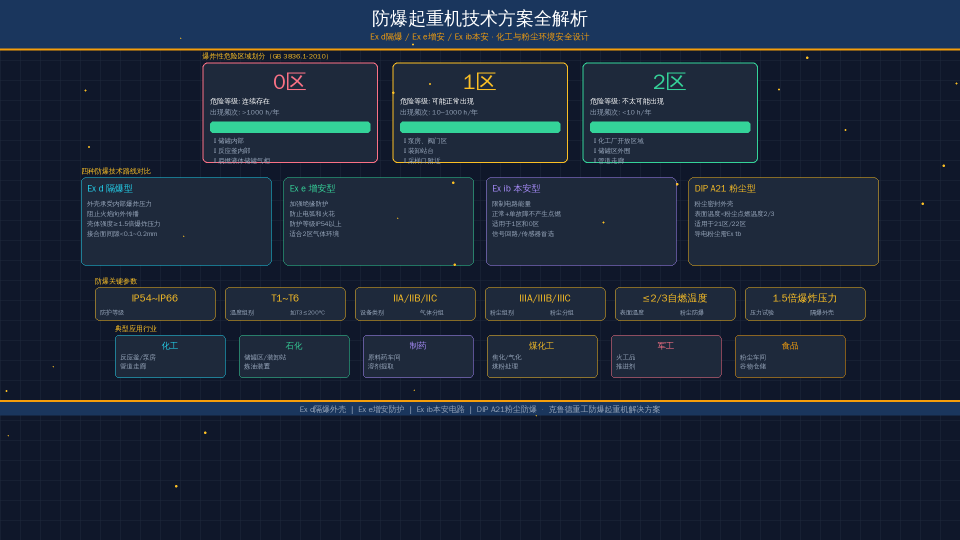
Increased Safety (Ex e) and Intrinsic Safety (Ex ib) are essential complementary technologies for explosion-proof cranes, ensuring safe operation in hazardous environments through different approaches. Ex e prevents the creation of ignition sources through enhanced measures, while Ex ib ensures that even if electrical sparks occur, they lack sufficient energy to ignite the explosive mixture.
Engineering implementation of Ex e technology on cranes primarily involves the following aspects: Enhanced electrical insulation is the top priority—motor windings use Class F or Class H insulation materials with vacuum pressure impregnation (VPI) processing to eliminate air gaps in the insulation, improving dielectric strength and thermal resistance. Next is the reliability of conductor connections—all terminal blocks use anti-loosening designs such as spring washers, double lock nuts, or toothed lock washers to prevent loosening under vibration. Third is increased creepage distances and clearances—per GB 3836.3-2010, Ex e equipment requires creepage distances 30% to 60% greater than standard equipment, with specific values depending on the comparative tracking index (CTI) of the insulation material.
In the design of Ex e control boxes for cranes, the following points require attention: the enclosure protection rating must be at least IP54 (IP65 is commonly required in practice) to prevent dust and moisture ingress; internal wiring must use flame-retardant cables secured with cable ducts or cable ties to prevent abrasion from vibration; temperature rise of all components must be strictly verified so that conductor and insulation temperatures do not exceed allowable limits under rated operating conditions; and spacing between terminal blocks must satisfy Ex e creepage distance requirements, with insulating diaphragms used to increase the path where necessary.
Application of Ex ib intrinsic safety in crane control systems has been a key technology driving the intelligent development of explosion-proof cranes since 2023. Intrinsically safe circuits use safety barriers (Zener barriers or isolated barriers) to limit energy, ensuring that any electrical spark energy produced under fault conditions remains below the minimum ignition energy of the explosive gas. For gases with low ignition energy such as hydrogen (20 μJ), Ex ib circuit design is particularly stringent.
In the wireless remote control system of explosion-proof cranes, Ex ib technology is widely applied: the input circuit of the remote receiver connects to the external antenna through an intrinsically safe isolating barrier, preventing externally induced electromagnetic energy from entering the hazardous area; control signal circuits use Ex ib intrinsic safety modules for isolation and energy limiting, keeping signal power entering the hazardous area below safe thresholds; and sensors (such as limit switches and load sensors) use Ex ib design, ensuring no ignition-capable sparks are produced even under internal short-circuit conditions.
Kelude's combined Ex e and Ex ib approach has delivered strong results in real-world projects. For example, in an explosion-proof crane project at a chemical plant, the main hoisting motor uses Ex d flameproof protection, the auxiliary control system uses Ex ib intrinsic safety, and the lighting and signaling systems use Ex e Increased Safety. The integration of all three types satisfies Zone 1 hazardous area safety requirements while balancing practicality and cost-effectiveness.
Dust Explosion Protection: DIP A21 Technical Approach for Cranes
Dust explosions are a critical safety hazard in the chemical and food processing industries. Per GB 12476.1-2013 (Electrical Apparatus for Use in the Presence of Combustible Dust), dust explosion protection differs significantly from gas explosion protection in technical approach. Explosion-proof cranes operating in dusty environments require the DIP (Dust Ignition Protection) technical route.
Characteristics of dust explosions dictate the focus of protection design. Unlike gas explosions, dust explosions require three simultaneous conditions: combustible dust suspended in air at an appropriate concentration (typically 20 to 60 g/m³ at the lower explosive limit), an ignition source (spark, arc, or hot surface), and an oxidizer (oxygen). Dust explosions are often more destructive than gas explosions because they typically involve secondary explosions—the shock wave from the initial explosion lifts accumulated dust, triggering a larger secondary explosion over a wider area.
DIP A21 Explosion Protection Class is the typical requirement for explosion-proof cranes operating in Zone 21 dusty environments. DIP A21 corresponds to the explosion protection level for Zone 1 gas environments and is suitable for locations where combustible dust atmospheres may occur during normal operation (Zone 21). Core design requirements for DIP A21 include: enclosure protection rating of at least IP6X (fully dust-tight) to prevent dust ingress into equipment; maximum surface temperature not exceeding two-thirds of the dust ignition temperature (for dust layers) or the dust cloud ignition temperature minus 75°C (whichever is lower); and enclosure design that prevents dust accumulation forming hot spots—achieved through sloped top surfaces (minimum 10° incline) to prevent dust settling.
Special design features of dust explosion-proof cranes span multiple aspects. Motors use dust flameproof (Ex tD) enclosures with increased fin spacing to prevent dust clogging, and the enclosure surfaces are coated with low-friction anti-static paint to prevent static charge accumulation. Brakes use sealed enclosures that fully contain friction sparks between the brake disc and brake pads. Crane rails and wheels incorporate special anti-static materials or grounding devices to ensure static electricity generated during operation is safely dissipated. Control boxes feature dust-tight sealed construction with an internal positive-pressure protection system that continuously supplies clean air to prevent dust ingress.
Kelude Heavy Industry's dust explosion-proof crane solutions are widely applied in flour processing, feed production, coal chemical, and similar industries. Taking the crushing workshop of a coal chemical plant as an example—a Zone 21 dusty area with coal dust (Kst value approximately 100–150 bar·m/s)—we supplied a DIP A21 bridge crane with a rated lifting capacity of 16 t and a span of 22.5 m. All electrical components use dust explosion-proof enclosures with a Temperature Class of T120°C (coal dust cloud ignition temperature is approximately 500°C, providing ample safety margin). The system is equipped with static grounding monitoring and online dust concentration detection, achieving over 5,000 hours of safe operation without incident.
Explosion-Proof Electrical Systems: Full-Chain Protection from Motor to Control Box
The electrical system of an explosion-proof crane is the core of safety assurance, covering full-chain protection from power supply entry to motor drive, and from control signals to operating commands. Failure of explosion protection at any single point can lead to serious consequences, which is why a systematic approach to explosion-proof design is essential.
Explosion-proof motor design and selection is the first step in electrical system protection. The hoisting motor, travel motor, and trolley motor of an explosion-proof crane must each be selected with the appropriate explosion protection type based on the hazardous area classification. Ex d flameproof motors are the most common in crane applications—their enclosures withstand internal explosions and quench flames through flameproof joints. Key design parameters for explosion-proof motors include: temperature rise limits at rated power (progressively decreasing from 450°C to 85°C across Temperature Classes T1 through T6), starting characteristics (starting current must not cause joint surface temperatures to exceed limits), and stall protection (thermal elements embedded in windings for real-time temperature monitoring). Kelude Heavy Industry employs dual temperature protection with PTC thermistors and explosion-proof thermal overload relays, ensuring motors never exceed Temperature Class limits under any abnormal condition.
Explosion-proof control boxes serve as the electrical system's control center. Ex d control boxes feature cast steel or steel-plate welded enclosures housing circuit breakers, contactors, VFDs, PLCs, and other electrical components. Design considerations include: heat dissipation of internal components—high-power VFDs require heat sinks or a combined Ex d enclosure with Ex e heat sink configuration; internal wiring using flame-retardant cables arranged by voltage level and current rating to avoid cross-interference; and flameproof joints between the control box door and body must be kept clean—rubber gaskets are not permitted (rubber is not an approved flameproof joint material).
Cable entry and routing is the most overlooked yet highest-failure-rate aspect of explosion-proof systems. Every cable crossing a hazardous area boundary—from the power supply inlet to motor leads—must use certified explosion-proof cable glands. GB 3836.15-2017 provides detailed requirements for cable entry: the difference between cable outer diameter and seal ring inner diameter must not exceed 1 mm; non-armored cables require anti-pull-out devices; and each core of multi-core cables must maintain adequate electrical clearance within the junction box. In Kelude Heavy Industry's practice, all cable entry points carry dual identification—gland numbers correspond one-to-one with wiring diagrams for accurate maintenance identification.
Grounding and equipotential bonding are equally critical in explosion-proof electrical systems. All metal parts of an explosion-proof crane—including rails, end carriages, trolley frame, hook block, and control box enclosures—must be reliably grounded with grounding resistance ≤ 4 Ω. Crane travel rails require bonding jumpers to ensure electrical continuity between rail sections. For explosion-proof cranes with VFD drives, high-frequency grounding and EMC filtering must also be considered to prevent harmonic coupling from the VFD into hazardous areas through the grounding system.
Signal and control circuit protection uses Ex ib intrinsic safety design. PLC digital input/output modules connect to field sensors through intrinsic safety barriers, while analog signals (such as VFD speed references and load sensor signals) use isolated safety barriers for energy limiting and signal conversion. The main circuits of operator stations—including remote controls, control grips, and control panels—use Ex d flameproof protection, while signal circuits use Ex ib intrinsic safety, ensuring that energy entering hazardous areas is strictly limited while operators remain in safe zones.
Crane Selection: Matching Duty Conditions with Safety Redundancy
Selecting an explosion-proof crane is critical to ensuring safe, reliable, and cost-effective operation. Unlike standard cranes, explosion-proof crane selection must comprehensively consider hazardous environment characteristics, duty requirements, safety redundancy, and maintenance accessibility.
Determine explosion protection type and class based on hazardous area classification. First identify the gas/dust grouping and Temperature Class of the operating area, then select the appropriate explosion protection level. For example: Zone 0 requires Ex ia equipment—crane installation in Zone 0 is generally not recommended (equipment should be minimized in Zone 0), but if absolutely necessary, an Ex ia combination scheme must be used; Zone 1 permits Ex d or Ex ib; Zone 2 permits Ex d, Ex e, or Ex n. For hydrogen environments common in the chemical industry (Group IIC, T1), motors and control boxes must be rated Ex d IIC T1 or Ex ib IIC T1, with Ex d enclosure gap design meeting Group IIC requirements (gap ≤ 0.1 mm).
Define crane duty parameters. These include lifting capacity (rated lifting capacity and maximum lifting capacity), span, lifting height, work duty (M1 to M8, selected based on frequency of use and load spectrum), and travel speeds (lifting speed, long-travel speed, cross-travel speed). Particular attention must be paid to the impact of work duty on explosion-proof design: equipment with high work duty (M6 to M8) experiences frequent start/stop cycles, placing greater thermal stress on motors and control boxes, requiring more precise temperature verification and heat dissipation design.
Incorporate safety redundancy. In hazardous environments, a single point of failure must not compromise safety functions. Recommended safety redundancy measures include: dual brake configuration on the hoisting mechanism (if one brake fails, the other still provides safe braking); dual-signal load limiter acquisition (mechanical plus electronic); limit switches with Ex ib intrinsic safety dual-channel configuration; and critical control signals using hard-wired safety circuits (independent of PLC). These redundancy features are standard configuration in Kelude Heavy Industry's explosion-proof crane products.
Evaluate special environmental factors. Beyond explosion hazards, consider temperature range (sealing materials become brittle at low temperatures, requiring low-temperature seal rings), humidity and corrosives (acidic or alkaline gases in chemical environments can corrode flameproof joints, requiring stainless steel or special coatings), dust characteristics (conductive dust such as aluminum powder requires a more stringent explosion protection class than ordinary dust), and vibration and shock (frequent start/stop vibration can loosen fasteners, requiring lock washers and thread-locking compounds).
Consider maintenance operations and lifecycle cost. Maintenance costs for explosion-proof cranes are significantly higher than for standard cranes. Selection should evaluate: availability and replacement difficulty of wear parts (bearings, seal rings, and other components of Ex d motors require periodic replacement—choose standard models that are readily available); maintenance access (flameproof enclosure disassembly requires specialized tools and adequate space); and spare parts inventory strategy (critical spare parts such as Ex d motors and explosion-proof cable glands should be stocked to avoid extended downtime).
Installation and Maintenance: Ensuring Long-Term Explosion Protection Performance
The quality of installation and maintenance directly determines an explosion-proof crane's safety performance throughout its service life. Even the best-designed explosion-proof equipment will rapidly degrade in protection capability if improperly installed or inadequately maintained, becoming a potential safety hazard. The following are core specification points for explosion-proof crane installation and maintenance.
Key installation requirements. Foundation and rail installation come first: the crane rail foundation must be level and solid, with rail installation accuracy meeting the requirements of GB/T 10183-2005, and explosion-proof bonding jumpers (copper braided tape with cross-section ≥ 25 mm²) installed at rail joints to ensure grounding continuity. Next is crane assembly: flameproof joints must be cleaned and coated with a thin layer of anti-rust grease (non-conductive) before assembly; fastening bolts must be tightened in stages to the specified torque values—impact wrenches are prohibited as they can damage joint surfaces. Finally, electrical installation: cable entry device seal rings must match cable outer diameters; cables entering junction boxes must maintain adequate bending radius (≥ 6 times cable outer diameter); and all intrinsic safety and non-intrinsic safety junction boxes must be clearly identified and separated by ≥ 50 mm.
Periodic explosion protection testing is the core of maintenance work. Per GB 3836.16-2017 and AQ 3009-2007, inspection intervals for explosion-proof cranes are: visual inspection (monthly), routine inspection (every 3–6 months), and detailed inspection (annually). Primary inspection items include: flameproof joint width and gap (measured with feeler gauges—wear exceeding allowable values requires repair or enclosure replacement); cable entry device sealing performance (visual and pressure testing to check seal ring aging or deformation); grounding resistance (measured with a ground resistance tester, not exceeding 4 Ω); temperature rise detection (using an infrared thermal imager after rated-load operation to verify enclosure temperature stays within Temperature Class limits); and insulation resistance measurement (motor winding-to-ground insulation resistance ≥ 5 MΩ).
Explosion safety measures during maintenance. When maintaining an explosion-proof crane in a hazardous area, the following rules must be observed: a hot work permit is required before any operation that could generate sparks (welding, grinding, etc.); the equipment must be disconnected from power, verified de-energized, and grounded/discharged before opening any Ex d enclosure; after opening an Ex d enclosure, flameproof joint surfaces must be carefully placed—never directly on the floor or workbench (place a rubber mat underneath); during reassembly, flameproof joints must be cleaned and coated with anti-rust grease, with tightening torque reaching 90%–110% of the specified value; and replacement parts must be original certified explosion-proof components—standard parts are not acceptable substitutes.
Kelude's Lifecycle Maintenance & Support Program covers every stage of your crane's service life. At delivery, you receive a detailed Explosion-Proof Maintenance Manual that includes a complete inventory of Ex-rated components with their certification numbers. We set up an equipment file for each crane, logging joint gap measurements from every inspection to track performance trends over time. Our Explosion-Proof Maintenance Training courses ensure your service personnel gain the specialized knowledge and hands-on skills required for safe work on Ex-rated equipment. We also operate a cloud-based spare parts inventory system, with critical explosion-proof components—such as flameproof motors, explosion-proof cable glands, and intrinsically safe modules—delivered to major industrial hubs within 36 hours.
Explosion-Proof Crane FAQ: Selection, Certification & Maintenance
Explosion-Proof Crane Design: A Systems Engineering Approach
Designing an explosion-proof crane is a multidisciplinary engineering effort that spans hazardous area classification, explosion protection class selection, mechanical design, electrical protection, dust ingress prevention, and installation & commissioning. As a leading explosion-proof crane manufacturer, Kelude has built extensive project experience across the chemical, petrochemical, pharmaceutical, coal chemical, and food processing industries. Our technical portfolio covers the full spectrum—from flameproof (Ex d) enclosures to intrinsically safe (Ex ib) systems, and from gas explosion protection to dust explosion protection.
A: Selecting the right explosion-proof crane is more than a matter of regulatory compliance—it is a fundamental safeguard for your assets and your people. Every step, from hazardous area classification to equipment selection, from installation & commissioning to routine maintenance, demands specialized expertise and rigorous execution. We hope this guide serves as a practical reference for your crane selection and technical solution design.
References & Applicable Standards
- GB 3836.1-2010 Explosive Atmospheres – Part 1: Equipment – General Requirements
- GB 3836.2-2010 Explosive Atmospheres – Part 2: Equipment Protected by Flameproof Enclosures "d"
- GB 12476.1-2013 Electrical Apparatus for Use in the Presence of Combustible Dust – Part 1: General Requirements
- ISO 4301 Crane Design Standard (corresponds to ISO 4301)
- GB 6067.1-2010 Safety Rules for Lifting Appliances – Part 1: General Requirements (corresponds to ISO 12480)
