

EPM Electromagnetic Permanent Magnet: Dual-Magnet Sync & PLC Control
Electro-permanent magnet (EPM) technology is the most technically advanced of the three main magnetic crane types. It uses neodymium-iron-boron (NdFeB) magnets to provide the primary holding force, while alnico (AlNiCo) acts as a "reversible switch magnet"—a pulse of current lasting less than 1 second flips the magnetization direction of the AlNiCo to switch between lifting and releasing modes. EPM combines the fail-safe holding of permanent magnets during power outages with the electrical controllability of electromagnets, and is replacing traditional electromagnetic chucks in unmanned overhead crane and automated production line applications at a growth rate exceeding 20% per year. This article breaks down EPM technology from four angles: dual-magnet synergy, pulse timing control, magnetic circuit switching dynamics, and PLC integration. Before explaining EPM, it helps to understand a counterintuitive physical fact: NdFeB magnets (with coercivity Hcj > 12 kOe) are extremely "stubborn" about their magnetization direction—ordinary electromagnetic fields simply cannot reverse it. The design genius of EPM lies in "division of labor"—NdFeB provides the constant primary holding force (its magnetization direction never changes), while AlNiCo (with coercivity Hcj of only about 0.5–1.5 kOe) acts as the "switch"—its magnetization direction can be flipped by a brief current pulse, thereby routing or blocking the magnetic circuit of the NdFeB.
The following technical analysis is based on the lifting spreader safety requirements of ISO 4301 Crane Design Standard—Core Provisions, combined with the magnetic circuit switching safety logic unique to EPM.
This is Part ③ of the magnetic crane series. For a full comparison of all three types and selection guidance, see the pillar page Magnetic Crane Type Selection Quick Reference
Dual-Magnet Synergy: NdFeB Provides the Force, AlNiCo Acts as the Switch
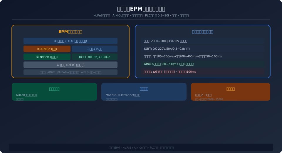
The EPM magnetic circuit consists of four layers (from the bottom working face upward): the pole face (DT4C electrical pure iron), the NdFeB permanent magnet (primary holding force source, e.g., N48SH with Br = 1.38 T), the AlNiCo reversible magnet (switch magnet, e.g., AlNiCo 5 with Br = 1.25 T and Hcj = 0.6 kOe), and the top yoke (DT4C pure iron, closing the magnetic circuit).
Holding state: The magnetization direction of AlNiCo is aligned with that of NdFeB (series-aiding configuration). The magnetic fluxes of both magnets combine at the bottom working face and within the workpiece, forming a strong flux loop that holds the load securely. In this state, the entire system operates as a zero-power static magnetic field—the core advantage of EPM.
Release state: A reverse current pulse (typically DC 220 V / 50 A / 0.3–0.8 s) is applied to the AlNiCo, generating a reverse magnetic field strength exceeding the coercivity of AlNiCo (Hcj = 0.6 kOe). The magnetization direction of AlNiCo is flipped to oppose that of NdFeB. The fluxes of AlNiCo and NdFeB then form an internal short-circuit loop within the top yoke, reducing the leakage flux at the bottom working face to near zero and releasing the workpiece.
Key parameters: The amplitude, pulse width, and waveform of the current pulse are controlled by an RC charge-discharge circuit or an IGBT chopper. The current amplitude must reach the minimum magnetic field strength H_sat required for saturation magnetization of AlNiCo (typically 3–5 times Hcj, i.e., about 2–3 kOe). The pulse width must cover the dynamic time of magnetic domain reversal (AlNiCo reversal time is approximately 50–200 ms, determined jointly by eddy currents and domain wall mobility). The waveform is typically square or exponentially decaying; square waves offer higher magnetization efficiency.
Pulse Timing Control: Why the EPM "Brain" Matters More Than the "Muscle"
The EPM controller is essentially a high-current pulse generator. The design challenge lies in releasing several hundred joules of energy in under 1 second (e.g., DC 220 V / 50 A / 0.5 s = 5,500 J) while precisely shaping the pulse waveform to prevent under-magnetization of AlNiCo (insufficient holding force) or over-magnetization (heating and demagnetization). Core controller components include: ① A charging capacitor bank (electrolytic capacitors, typically 2,000–5,000 μF / 450 V total)—pre-charged to 300–400 V before the pulse, with discharge controlled via IGBT; ② An IGBT switch module (e.g., Infineon FF300R12KE3)—controls the on/off timing of the pulse with a response time of under 1 μs; ③ A freewheeling diode—provides an inductive current path after IGBT turn-off, preventing high-voltage spikes from damaging the IGBT; ④ A current sensor (Hall-effect type, ±1% FS accuracy)—monitors the pulse current in real time and feeds it back to the MCU for closed-loop control. The pulse timing typically follows a three-stage sequence: pre-magnetization (100–200 ms, current ramps to target value), main magnetization (200–400 ms, current holds at plateau level), and demagnetization/energy recovery (50–100 ms, IGBT turns off, inductive energy returns to the capacitor bank via the freewheeling diode, with an energy recovery rate of about 30–50%). The controller also implements the following safety redundancy functions: ① Magnetization completion verification—after the pulse, residual magnetic field strength at the pole face is checked (via Hall sensor); if below the set threshold, an alarm is triggered and lifting is prohibited; ② Dual-channel independent control—two AlNiCo magnets are driven by two independent IGBT channels, so a fault in one channel does not affect the other (redundant design); ③ Capacitor health monitoring—an alarm is issued when capacitance degradation exceeds 15% (capacitor aging can lead to insufficient pulse energy and incomplete magnetization).
Magnetic Circuit Switching Dynamics: The Physics Behind the Sub-Second Switch
The magnetization reversal of AlNiCo magnets under a current pulse is not instantaneous—it is a complex dynamic process involving domain wall motion, eddy current damping, and thermal effects.
The reversal time τ = τ_mag + τ_eddy, where τ_mag is the domain wall motion time (approximately 50–150 ms for AlNiCo) and τ_eddy is the eddy current damping time (dependent on the magnet's resistivity and geometry; for AlNiCo with resistivity ρ ≈ 0.45 μΩ·m and a 10 × 10 × 5 mm magnet, τ_eddy ≈ 30–80 ms). The total reversal time is approximately 80–230 ms—which is why EPM pulse widths are typically set to 300–800 ms (including safety margin).
Two physical effects require attention during the reversal process: ① Eddy current heating—the eddy currents induced inside the AlNiCo magnet by the pulse generate Joule heat ΔT = I²_eddy × R × t. While a single pulse typically causes a temperature rise of under 5 °C, repeated high-frequency lift/release cycles (e.g., more than 10 cycles per minute) can lead to cumulative heating. The controller must therefore impose a duty cycle limit (e.g., ≤ 6 cycles per minute) or incorporate additional heat dissipation design; ② Magnetic after-effect—AlNiCo requires approximately 50–100 ms of "magnetic stabilization time" after the pulse ends, during which the magnetization strength still exhibits minor fluctuations. The controller must delay the "magnetization complete" signal by 100 ms before sending it.
PLC Integration and Unmanned Overhead Crane Solutions
The greatest application value of EPM lies in its seamless integration with PLC/robotic control systems—because it requires no manual Control Grip, operating instead through electrical signals for lift and release, something a Permanent Magnet Lifter cannot achieve.
A typical EPM + PLC integration scheme: The PLC communicates with the EPM controller via Modbus TCP/RTU or Profinet, sending "engage" or "release" commands. The EPM controller executes the pulse magnetization/demagnetization cycle and returns a status signal (OK / fault / charging) upon completion. The PLC then proceeds with the next logic step based on the status (e.g., OK → crane hoisting; fault → alarm and stop). The entire process—from PLC command to EPM lift/release completion plus status feedback—takes under 2 seconds. In unmanned overhead crane scenarios, the EPM also coordinates with the crane's anti-sway control system and machine vision system: the vision system confirms workpiece position and orientation → the crane moves to the target position → the EPM holding force sensor confirms adequate gripping force → the crane hoists → the anti-sway system stabilizes the lifting spreader → the crane travels to the target position → the EPM releases. The entire sequence is fully automated with no manual intervention.
Electro-Permanent Magnet EPM Selection Parameter Quick Reference
| Parameter | Small | Medium | Large |
|---|---|---|---|
| Holding Force | 0.5~3t | 3~10t | 10~20t |
| Pulse Current | 50~100A/1ms | 100~200A/2ms | 200~400A/3ms |
| Pick-and-Release Time | <0.5s | <0.8s | <1.0s |
| Magnetic Pole Zoning | 2Zone | 2~4Zone | 4Zone |
| Safety factor | ≥3.5 | ≥3.5 | ≥3.5 |
| PLCInterface | DI/DO+Modbus | DI/DO+Profinet | DI/DO+Ether CAT |
| Reference Price | ¥8,000~20,000 | ¥20,000~50,000 | ¥50,000~100,000 |
EPM vs. Permanent Magnet Lifter: FAQs
Q: What's the difference between an EPM and a permanent magnet lifter? Aren't they both permanent magnets?
A: The fundamental difference lies in how the magnetic circuit is switched. A permanent magnet lifter uses a mechanical handle to rotate the magnetic circuit (purely mechanical), while an EPM uses a current pulse to reverse the magnetization of AlNiCo magnets (electrical). This means an EPM can be integrated with PLC remote control and automation systems, whereas a permanent magnet lifter requires manual operation. The trade-off is that EPMs cost 2–3 times more and require a controller and power supply lines.
Q: Will an EPM lose its magnetic force during a power outage?
A: No. An EPM only requires a current pulse (less than 1 second) during the pick-up and release cycles. At all other times, the holding force is maintained entirely by the permanent magnets—so even with a complete power failure, the lifting force is not lost. This is the key safety advantage of EPMs over lifting magnets.
Q: Why are EPMs so much more expensive than lifting magnets? Is it worth it?
A: The cost difference comes from three factors: ① Dual magnets (NdFeB + AlNiCo), with raw material costs roughly 1.5–2 times that of a single-magnet design; ② The IGBT pulse controller (including capacitor bank and sensors), priced at approximately $300–$740 per unit; ③ Complex assembly and magnetization processes. However, the total cost of ownership (TCO) advantage of EPMs is significant: zero running power consumption (saving roughly $740–$1,480 per year in electricity), no UPS maintenance (no batteries required), and seamless integration with unmanned overhead cranes (reducing manpower by 1–2 operators per shift). For production lines operating continuously (more than 300 days per year), the incremental investment in an EPM can be recovered within 2–3 years through combined electricity and labor savings.
—
Standards: ISO 4301, GB/T 13560-2017
