

Anti-Sway Control for Smart Cranes
📋 Key Summary
Smart cranes utilize anti-sway technology to strictly limit spreader swing angles to within 0.5 degrees, achieving millimeter-level positioning accuracy of 2 mm. In high-end customization scenarios for European-standard double-girder cranes ranging from 50t to 300t, the main hoisting speed reaches 10 m/min, significantly enhancing operating stability. This drastically reduces material loss and ensures rock-solid lifting safety, providing a reliable foundation for heavy equipment manufacturing and logistics handling.
In the fields of heavy equipment manufacturing and large-scale logistics handling, spreader sway has long been a critical factor affecting operational efficiency and safety. Kelude Heavy Industry specializes in high-end customization for European-standard double-girder cranes (50t–300t), deeply integrating intelligent anti-sway technology into crane control systems. During the design and manufacturing process, our technical team strictly adheres to the dynamics and structural strength requirements outlined in FEM 1.001 Crane Design Specification, ensuring stability under complex working conditions. Simultaneously, at the safety supervision and acceptance levels, we fully comply with all technical indicators of the TSG 51-2023 Safety Technical Supervision Regulation, laying a solid foundation for the reliable operation of smart cranes.
Precision Control of Spreader Swing via Anti-Sway Algorithms
In terms of hardware configuration, the system typically installs high-precision inclination sensors beneath the trolley frame and equips absolute encoders at the hoisting mechanism drums. With a sampling frequency of 1000 Hz, these inclination sensors capture minute changes in the spreader’s spatial attitude at millisecond speeds. This data is transmitted in real-time to the PLC controller via industrial Ethernet, where it undergoes filtering and calculation to generate precise speed compensation commands. Regarding the application of AI anti-sway algorithms in heavy lifting, the system achieves real-time reconstruction of the spreader’s three-dimensional spatial attitude through multi-source data fusion.
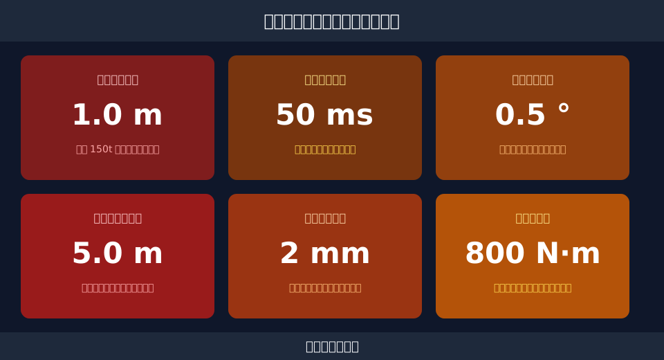
In practical tests involving a 100t European-standard double-girder crane, when the bridge travel started at 80 m/min, the spreader swing angle under traditional open-loop control reached 3.5 degrees. By introducing closed-loop anti-sway algorithms, the system response time was reduced to within 50 ms, strictly suppressing the spreader swing angle to less than 0.5 degrees.
The core of the algorithm lies in the precise calculation of the sway period. For a spreader with a rope length of 15 m, the theoretical sway period is approximately 7.7 seconds. Based on this period, the control system automatically adjusts the motor output frequency during acceleration and deceleration phases, allowing the inertia force generated by acceleration to cancel out the gravitational restoring force, thereby ensuring smooth operation.
Braking Distance Calculation for Double-Girder Cranes Under Heavy Loads
Under heavy-load conditions, the reliability of the braking system directly impacts operational safety. Taking the crane travel mechanism as an example, precise calculation of the braking distance is essential to ensure the equipment stops smoothly in emergency situations. Consider a 150t European-standard double-girder crane with a rated long travel speed of 60 m/min, which converts to 1 m/s. During full-load braking, the set average deceleration is 0.5 m/s². According to kinematic formulas, the braking distance $s$ is calculated as follows: $s = v^2 / (2a) = 1^2 / (2 \times 0.5) = 1$ m. This means that at full speed, the bridge travels only 1 m from the start of braking to a complete stop.
Braking time is equally critical. Using the formula $t = v / a$, the braking time $t = 1 / 0.5 = 2$ s. During these 2 seconds, the anti-sway system intervenes synchronously, adjusting the operating status of the hoisting and trolley mechanisms to prevent severe front-to-back swinging caused by sudden bridge stops. This precise braking control keeps positioning errors within 2 mm when docking and installing large components up to 300t.
To achieve the aforementioned 1 m braking distance, brake selection is crucial. The crane travel mechanism is typically equipped with double brakes, each requiring a braking torque of over 800 N·m. During braking, the brakes employ a staged release and closure strategy to avoid mechanical shock caused by sudden changes in braking force. This soft braking method not only protects the wheels and rails but also buys valuable adjustment time for the anti-sway system.
Structural Welding and Main Girder Force Analysis in High-End Custom Cranes
The structural strength of high-end custom cranes serves as the physical foundation for the anti-sway system. In main girder design, Kelude Heavy Industry uses Q355B high-strength low-alloy structural steel, which boasts a yield strength of 355 MPa, providing ample stiffness reserves for the equipment. According to design specifications, the static stiffness of double-girder crane main girders must satisfy the deflection limit $f \le L/800$ (where $L$ is the span). For a 200t crane with a span of 28.5 m, the allowable static deflection is $28500 / 800 = 35.6$ mm. In actual manufacturing, finite element analysis optimizes the box girder structure, keeping the actual mid-span deflection of the main girder within 22 mm, effectively reducing lifting height variations and spreaderSway caused by main girder deformation.
Regarding welding procedures, first-class weld seams in the tensile zone of the main girder require 100% non-destructive testing, while the inspection ratio for second-class weld seams in the compressive zone must be no less than 20%. For specific detection techniques, refer to Main Girder Weld Crack Detection and Non-Destructive Testing Technology. Through dual ultrasonic and radiographic inspections, we ensure the absence of internal defects such as porosity and slag inclusion in weld seams, guaranteeing fatigue life under long-term alternating loads.
Beyond the main girder structure, rail installation accuracy also affects anti-sway performance. Rail span deviations must be controlled within ±5 mm, and the height difference at rail joints must not exceed 1 mm. If the rails exhibit significant waviness, additional lateral excitation forces will arise during bridge travel. These external interferences superimpose onto the spreader’s sway, increasing the difficulty of algorithmic compensation. Therefore, strict calibration of rail geometric dimensions is mandatory during the installation phase.
Electrical Control Systems and Anti-Collision Safety Distances in Smart Cranes
The electrical control system of smart cranes must remain stable in complex environments. Kelude Heavy Industry’s electrical cabinets feature an IP54 protection rating, effectively resisting dust and moisture intrusion from workshops. The operating temperature range is set between -20°C and 50°C, ensuring that frequency inverters and PLCs continue to function normally even under extreme climatic conditions. Regarding electromagnetic compatibility, large variable-frequency equipment and welding machines in workshops can easily generate electromagnetic interference. Inside the electrical cabinet, double-layer shielded cables are used, with signal cables and power lines laid separately at a spacing of over 200 mm. Additionally, optocouplers are installed on the PLC input and output modules to ensure stable transmission of anti-sway control signals even in strong electromagnetic environments.
In workshops with multi-crane collaborative operations, the anti-collision system is an indispensable safety barrier. Regarding Crane Anti-Collision Safety Distance Setting Standards, the system uses LiDAR and ultrasonic sensors to monitor distances between adjacent equipment in real-time. When two 100t cranes operate on the same track and the relative distance shrinks to 5 m, the system triggers a Level 1 warning, automatically reducing the long travel speed to 20 m/min. When the distance further shortens to the set safety distance of 2 m, the system directly cuts off the control circuit for the direction of travel, implementing emergency braking to prevent equipment collision.
| Comparison Parameter | Traditional Open-Loopcrane | Intelligentanti-sway controlcrane |
|---|---|---|
| Lifting spreaderSwingAnglecontrol system | Start-up andBrakingAchievable at 3°~5° | Full Strokecontrol systemWithin 0.5° Within |
| End PointPositioning Accuracy | Dependent onoperatorExperience-based,Error ±50mm | Automaticfine-tuning,Error ±2mm |
| Operationcycle time | Requires WaitingLifting spreaderStationary,Approximately 45s | No Wait Required,Approximately 15s |
| structural componentFatigueDamage | AlternatingStressLarge,service lifeShorter | smooth operation,service lifeExtended 20% |
FAQ
Q: Does the Anti-Sway System have specific Lifting Height requirements?
A: The accuracy of the anti-sway algorithm is closely tied to the rope length of the lifting spreader. A Lifting Height of at least 26 ft (8 m) is typically required to ensure sensors can accurately capture the sway cycle. When the rope length is below 16 ft (5 m), the sway period becomes too short, increasing system response difficulty. In such cases, we recommend combining the system with a mechanical anti-sway device for optimal control.
Q: Is there a difference in anti-sway performance between full-load and no-load conditions?
A: Yes, there are differences. Under full-load conditions, the greater mass and inertia of the lifting spreader result in higher sway energy, requiring the algorithm to output larger counter-torque. Kelude Heavy Industry’s Smart Crane systems feature a load-adaptive module that automatically adjusts control parameters based on Lifting Capacity. This ensures that swing angles remain within 0.5 degrees across various loads ranging from 55 tons to 330 tons (50t–300t).
Q: Does an Anti-Sway System failure disrupt normal operations?
No. The Smart Crane’s anti-sway control system utilizes a bypass design. If abnormal sensor signals or algorithm module faults are detected, the system automatically switches to traditional Open-Loop Control mode. The crane continues to operate normally, though the operator must manually manage acceleration and deceleration rhythms. This ensures production continuity without downtime caused by system failures.
Q: What is the typical delivery lead time for custom Smart Cranes?
For high-end customization projects involving European Standard Double-Girder cranes with capacities from 55 tons to 330 tons (50t–300t), complex structural design and electrical commissioning are involved. The standard delivery lead time is typically 90 to 120 days. Specific timelines depend on factors such as workshop Span, Lifting Height, and special anti-corrosion requirements. Final delivery times and project costs are subject to the actual contract.
