

Four-Rope vs. Multi-Jaw Grab for Waste-to-Energy Plants
The first question waste-to-energy plants face when purchasing a grab is "four-rope or multi-shell." This choice isn't about price—it's about whether your waste is being fed into the furnace or pulled from the bottom of a pit. The answer lies in three numbers: feed cycle time, waste density, and slag removal depth.
What Waste Is a Four-Rope Grab Best Suited For?
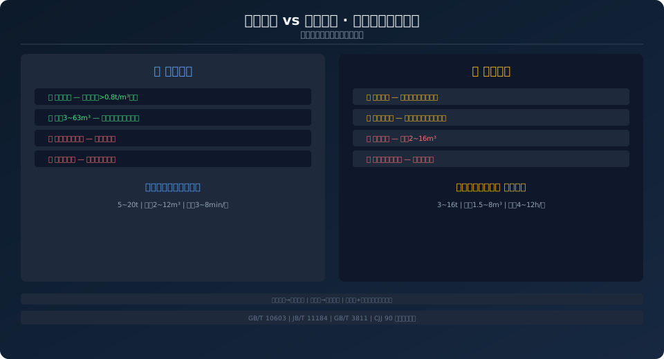
A four-rope grab's open-close force isn't limited by a hydraulic system, allowing it to easily handle materials with a density above 0.8 t/m³. In waste-to-energy plants, after 5–7 days of fermentation and dewatering, municipal solid waste reaches a density of 0.6–0.9 t/m³—right in the sweet spot. Wire rope service life ranges from 8,000 to 12,000 hours (referencing ISO 4301M5~M6 work duty classification), which is 2–3 times longer than the seal replacement interval of a hydraulic grab of the same capacity. However, the four-rope grab has larger closing clearances and struggles to grip bulky construction debris, which can easily slip out.
When Is a Multi-Shell Grab Absolutely Necessary?
Slag pit cleaning is the classic scenario. The pit floor is uneven with hardened slag, and a four-rope grab's jaws can't conform to irregular surfaces, achieving only a 50%–60% recovery rate. A multi-shell grab features independently hinged shells that can open nearly 180°, reaching recovery rates above 85%. Hydraulic drive with continuous pressure holding is especially critical for wet waste with over 50% moisture content—while a four-rope grab's tension fluctuates with material load, a hydraulic grab's cylinders maintain steady pressure. The trade-off is seal replacement every 2,000–3,000 hours, and the hydraulic power unit requires a 3 μm precision filter.
How Do You Determine the Feed Cycle?
It's calculated from the waste pit volume (2,000–8,000 m³), single-grab capacity, and the incinerator feed rate (200–600 t/d). For a 600 t/d plant, each grab cycle handles roughly 3–5 tons, runs every 6 minutes, and totals about 120 cycles per day. The most common cause of cycle overruns is excessive traverse distance—if the pit exceeds 40 m in length, a semi-automatic PLC path optimization is recommended to cut traverse time by 15%–25%.
Should the Slag Pit Have a Dedicated Grab?
Absolutely, if the budget allows. Slag temperatures reach 80–150°C, with moisture, acidity, and unburned chunks—sharing a grab means switching between two extreme operating conditions: feeding and slag removal. Field data shows shared wire rope life drops by 40%–50%, and seal replacements double. A dedicated setup adds roughly 30% to initial investment but saves over 60% in three-year maintenance costs.
Three Configurations for the Feed Platform
| Solution | Configuration | Processing Capacity | Application |
|---|---|---|---|
| Single Grab (grab bucket)+Direct Feeding | 1Four-Rope Direct Feeding Unit | ≤300t/d | Small-Scale Incineration Plant |
| Twin Grab (grab bucket)+Slewing | Four-Rope Feeding+Multi-Jaw Clamshell Ash Removal | 300~800t/d | Optimal for Medium-to-Large Plants |
| Independent Dual-Girder Trolleys | Each Equipped with Independent Overhead Crane Grab (grab bucket) | ≥800t/d | Redundant Configuration for Ultra-Large Plants Reset Switch |
How Waste Pit Management Affects Grab Selection
Most people focus on grab specifications while overlooking a critical prerequisite—how the waste pit is managed directly determines how the grab should be configured. A waste pit is not simply a dug-out basin. A well-designed pit follows the "first-in, first-out" principle: fresh waste is discharged from one side while aged waste is retrieved from the other. Without zoned management, fresh and aged waste mix together, and the grab ends up handling a "random blend" with fluctuating density, moisture content, and calorific value. This not only undermines grabbing efficiency but also directly compromises combustion stability in the incinerator.
Specifically, zoned waste pit management hinges on three key parameters:
① Waste stacking height—maintained at 60%–80% of the pit depth. Stacking too high compacts the bottom layer excessively, making grab penetration difficult; stacking too low exposes a larger surface area, worsening odor diffusion.
② Distribution strategy—fresh waste is discharged at the edge of the "aging zone" and layered progressively with the grab, creating a "sloped distribution" rather than a "mounded pile."
③ Aging time—municipal solid waste requires at least 5–7 days of fermentation to reach optimal combustion moisture content (40%–50%). These three parameters dictate the grab's pickup position, depth, and frequency. If pit management is chaotic, even the best grab cannot perform to its design capability.
Cycle Time Analysis for Grab Operations
Many assume grab selection boils down to three numbers: lifting capacity, bucket volume, and power. In reality, true efficiency depends on the operating cycle—the precise time allocation of a complete working cycle. Using actual operating data from a 10t four-rope grab at a 600 t/day waste-to-energy plant, a standard cycle breaks down as follows: grabbing phase 3–8 seconds (depending on waste density and bucket volume), lifting phase 15–25 seconds (at approximately 18 m lifting height), traversing phase 60–120 seconds (across a 30–50 m pit length), discharge phase 3–5 seconds, return phase 60–120 seconds, and positioning phase 15–25 seconds. Total cycle time ranges from 160 to 300 seconds—roughly 2.7 to 5 minutes per cycle.
Traversing time is the biggest variable: every additional 10 m of pit length adds approximately 20–30 seconds of traverse time and increases cycle time by 12%–18%. This is why pits exceeding 40 m strongly warrant semi-automatic PLC-based path optimization. The PLC automatically plans the shortest traverse route based on waste pile position and pre-accelerates the crane bridge during the grab's lifting/lowering time window, compressing traverse time by 15%–25%. Furthermore, higher travel speeds for the crane bridge and trolley are not always better—increasing speed from 40 m/min to 63 m/min does cut traverse time from 90 seconds to 57 seconds, but the dynamic load factor on the bridge structure jumps from 1.2 to 1.5, reducing main girder and end carriage fatigue life by 30%. Speed selection is a trade-off between structural fatigue and operational efficiency—bigger is not always better.
Five Common Grab Failures in Ash Removal Service
| Fault Symptom | Root Cause | Corrective Action | Preventive Maintenance Interval |
|---|---|---|---|
| Hydraulic Cylinder Oil Leakage | Caused by High Temperature Sealing Material Hardening | Replace with FKMFKM (Fluororubber)Sealing, Temperature Resistance250°C | Every2000hInspection |
| Clamshell Bucket Jaw Deformation | Impact from Unburned Oversized Hard Objects | Hardfacing Wear Layer on Tooth Tips, Ribbed Reinforcement Plate on Bucket Shell | Quarterly PTFlaw detection |
| Sensor False Alarm | Steam Condensation+Dust Accumulation | Replace IP67Protection Rating (IP)+Anti-Condensation Heater | Monthly Cleaning Calibration |
| Wire Rope Accelerated Wire Breakage | Acidic Vapor Corrosion+Alternating Bending | Replace Galvanizing Wire Rope+Increasesheave diameter | Monthly Flaw detection |
| Hydraulic Oil Emulsification | Moisture Ingress frombreather Entering Oil Tank | Install Desiccant-Typebreather+Entering Oil Tank Heater | Quarterly Oil Sample Analysis |
Slag-removal grabs typically fail 2–3 times more often than feed grabs—not because of poor design, but because slag removal is the harshest duty cycle a crane grab can face: high temperature (80–150°C) + high humidity (steam) + high corrosion (acidic gases) + high impact (unburned hard lumps). When all four stressors act simultaneously, any weak link in protection triggers a chain reaction. For example, a failed seal ring on the hydraulic cylinder leads to hydraulic oil leakage, which drops the operating pressure, which weakens grab closure, which leaves slag unremoved, which builds up on the pit floor, which the grab then slams into on the next cycle, deforming the shell—one failed seal ring ultimately destroys the grab structure. That's why slag-grab maintenance must shift from "fix when broken" to condition-based preventive maintenance: using vibration sensors, in-line oil monitoring, and thermal imaging to catch failures before they escalate.
Grab Crane Maintenance FAQs
Q: How often should four-rope grab wire ropes be replaced?
A: Under ISO 4309 inspection criteria in waste-to-energy service, wire rope life is 8,000–12,000 operating hours or 12–18 months. Replace immediately if 6 broken wires are found within 6 diameters, 12 within 30 diameters, or if rope diameter is reduced by more than 7%. Monthly wire rope flaw detection is recommended.
Q: How often should hydraulic oil in a multi-shell grab be changed?
A: First change after 500 hours, then every 2,000 hours or 6 months. Use ISO VG46 anti-wear hydraulic oil with NAS 1638 cleanliness class ≤8. The hydraulic power unit must be fitted with a 3-micron precision filter.
Q: What measures are needed for grabs operating at 80°C?
A: Three critical items: ① Use PP or steel-core wire rope; ② Pack jaw bearings with high-temperature grease with a dropping point ≥220°C; ③ Replace limit switches with non-contact inductive or reed types to prevent spring annealing and contact failure at high temperatures.
Q: What should be considered when grabbing wet waste with 60% moisture content?
A: Bucket capacity must be verified against wet waste density. Raw refuse can reach 0.9–1.1 t/m³—up to 60% denser than fermented waste. When grabbing raw waste, limit bucket fill to 60% of rated capacity, or the overload protection will activate.
For grab crane selection in waste-to-energy plants, contact the Kelude Heavy Industry engineering team—integrated design from waste pit layout to grab configuration.
