

GB/T 13752 Tower Crane Load Combinations and Checks
GB/T 13752-2017, the dedicated design standard for tower cranes, stands independently from GB/T 3811-2008 and applies to top-slewing, bottom-slewing, luffing-jib, and flat-top tower cranes. The standard defines six load combination cases, seven structural strength and stiffness verification indicators, five anti-overturning stability check scenarios, and design parameter requirements for hoisting, luffing, and slewing mechanisms as well as tie-in assemblies. Drawing on Kelude's tower crane design experience, this article breaks down the core provisions clause by clause.
GB/T 13752 vs. GB/T 3811: What Are the Key Differences for Tower Crane Design?
GB/T 13752-2017 is a dedicated design and calculation standard for tower cranes. Its most fundamental difference from the general-purpose GB/T 3811-2008 Crane Design Standard lies in design philosophy and scope of application. GB/T 3811 covers all crane types—overhead, gantry, tower, mobile, railway, and floating—providing a universal design framework. GB/T 13752, by contrast, is tailored specifically to tower cranes, with more granular provisions for load values, load combinations, partial safety factors, and stability verification methods.
The differences play out across four dimensions:
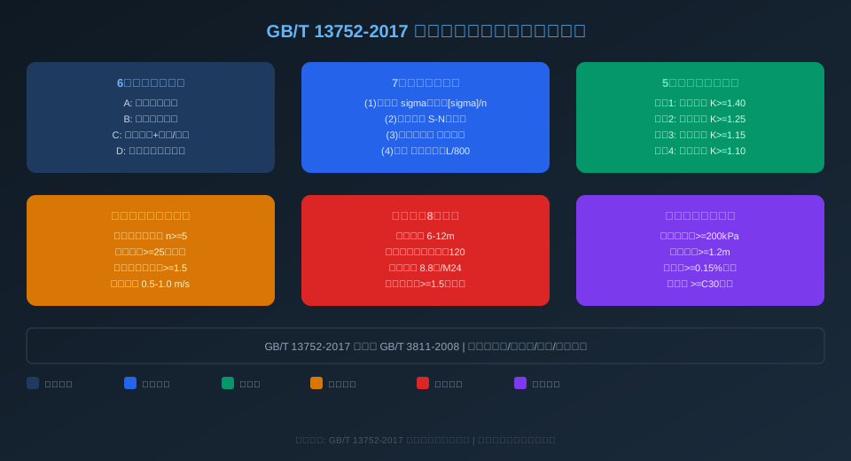
1. Load combinations. GB/T 3811 defines nine load combinations across three grades (A/B/C), whereas GB/T 13752 breaks tower crane working states into six specific combination cases: normal operation without wind (Case A), normal operation with wind (Case B), erection and dismantling (Case C), non-working wind load (Case D), buffer impact (Case E), and test loads (Case F). Each case has its own table of partial safety factors.
2. More refined wind load calculations. GB/T 13752 introduces height-segmented wind pressure correction factors for the tower mast, shielding reduction factors, and tower crane group interference coefficients. Working-state wind pressure is set at 250 Pa, while non-working-state wind pressure follows the regional basic wind pressure (which can exceed 1,000 Pa in coastal areas).
3. Stability verification gets its own chapter. Chapter 8 of GB/T 13752 specifies five anti-overturning check scenarios with corresponding safety factor K requirements, mandating separate verification of overall anti-overturning stability in both working and non-working states.
4. Dedicated chapter on tie-in assemblies. Chapter 9 details tie-in spacing, member slenderness limits (max 120), connection bolt grade (min 8.8), and embedded part pull-out safety factors (min 1.5)—none of which are addressed in GB/T 3811.
| Comparison Parameter | GB/T 3811 Crane Design Standard-2008 | GB/T 13752-2017 |
|---|---|---|
| Scope of Application | All Typescrane | Tower Crane Dedicated |
| Load combination Quantity | 9 Types(A/B/CLevel III) | 6Specific Combined Load Cases |
| Windload gauge Calculation | General Wind Pressure Coefficient | Segmental Correction+Group Tower Interference |
| Stability Verification | General Requirements | 5Load Cases+Independent Safety factor |
| Tie-in Device Design | Not Covered | Dedicated Chapter Provisions8Item Parameter |
| Sub-item Coefficient Value Determination | General Value Table | Tower Crane Specific Values |
How to Determine Load Combinations and Partial Safety Factors for Tower Cranes
Per Chapter 5 of GB/T 13752-2017, tower crane design must account for six load combination cases, each with its own set of load components and partial safety factors. Kelude applies this classification systematically across all structural calculations for its tower cranes.
Combination A — Normal Operation, No Wind: Lifting load × 1.22 + dead weight × 1.16 + horizontal inertia force × 1.0. This is the most fundamental duty case for everyday hoisting operations and applies to indoor or sheltered environments. The 1.22 partial factor on the lifting load reflects the influence of the dynamic load factor during hoisting.
Combination B — Normal Operation, With Wind: Lifting load × 1.22 + dead weight × 1.16 + horizontal inertia force × 1.0 + operating wind load × 1.0. This case covers outdoor service conditions, with an operating wind pressure of 250 Pa and a wind speed of 20 m/s. Note that for tower heights exceeding 30 m, a segmented wind-speed correction must be applied.
Combination C — Special Loads (Erection & Dismantling): Dead weight × 1.10 + erection dynamic load × 1.10 + wind load × 1.0. During jacking, lowering, and dismantling operations, the structural system changes as mast sections are partially connected. Although the partial safety factors are significantly reduced in this case, the load-bearing capacity of the connection bolts and the jacking cage must be verified separately.
Combination D — Out-of-Service Condition: Dead weight × 1.0 + out-of-service wind load × 1.0. The wind pressure is based on the 50-year return period basic wind pressure for the installation site: 800–1,000 Pa in coastal regions and 400–600 Pa inland. This represents the extreme wind-loading scenario for a crane in its parked configuration.
Combination E — Buffer Impact: Dead weight × 1.0 + buffer force × 1.0. When the crane jib may collide with adjacent structures or other tower cranes, the energy-absorption capacity of the buffer devices must be verified.
Combination F — Test Loads: The static load test is conducted at 1.25 times the rated lifting capacity, and the dynamic load test at 1.1 times. All partial safety factors are taken as 1.0 during testing, since wind and other accidental loads are not permitted to be superimposed on test conditions.
7 Strength and Stiffness Verification Parameters for Tower Crane Steel Structures
Chapters 6 and 7 of GB/T 13752-2017 define the verification methodology for strength and stiffness of tower crane steel structures, covering seven core check indicators. At Kelude, these seven indicators form the backbone of the structural safety validation process for every crane model.
1. Static Strength Verification. For each load combination case, the calculated stress in any member must not exceed the allowable stress, which equals the material yield strength divided by the safety factor n. For Q355B steel (≈S355JR), the yield strength is 355 MPa. The safety factor n is taken as 1.48 for Combinations A and B, 1.34 for Combination C, and 1.22 for Combination D.
2. Fatigue Strength Verification. For cranes with a working classification of A4 and above, fatigue life assessment is required for critical weld seams and stress-concentration zones. The stress-range method is applied, with allowable stress ranges determined from S-N curves. The design stress range must not exceed the allowable value divided by the fatigue resistance partial factor (1.0–1.35).
3. Elastic Stability Verification. Compression members — such as mast main chords and tie-in struts — must be checked for both overall and local stability. The effective cross-section method is used to calculate buckling resistance, and the critical stress must not exceed the material's proportional limit.
4. Stiffness Verification. Deflection limits for the crane structure are controlled under the serviceability limit state: the horizontal displacement at the top of the mast must not exceed H/800 (where H is the free height of the mast), and the downward deflection at the jib tip must not exceed L/500 (where L is the jib length).
5. Connection Strength Verification. Fillet welds are designed with a leg size of no less than 0.7 times the thinner plate thickness, and the calculated weld stress must not exceed 0.9 times the allowable stress. High-strength bolts are designed as friction-type connections, with the pretension force P taken in accordance with GB 50017.
6. Local Plate Stability Verification. Local buckling must be checked in areas such as mast section lacing bar gusset plates and the slewing bearing mounting plate. The width-to-thickness ratio is limited to b/t ≤ 42 for Q355 steel.
7. Natural Frequency Verification. The crane's fundamental natural frequency must avoid the wind-induced vortex shedding frequency range (0.2–0.4 Hz) and the load-swing frequency range (0.05–0.15 Hz) to prevent coupled resonance.
| Verification Items | Standard Clause Number | Governing Indicatorand Limits |
|---|---|---|
| Static Strength | Clause6.2Article | Calculated Stress Not Exceeding Yield/n, n=1.22~1.48 |
| Fatigue Strength | Clause6.3Article | Stress Range Not Exceeding Allowable Value/Sub-item Coefficient |
| Elasticity Stability | Clause6.4Article | Buckling Capacity Not Exceeding Material Proportional Limit |
| Structure Stiffness | Clause7.2Article | Tower Top Deflection Not Exceeding H/800, Jib Tip Deflection Tower Top Deflection Not Exceeding L/500 |
| Connection Verification | Clause6.5Article | Fillet weld Fillet Weld Leg>=0.7Times Plate Thickness, Weld Seam Stress<=0.9Times Allowable |
| Local Stability | Clause6.6Article | Width-to-Thickness Ratiob/t Tower Top Deflection Not Exceeding42(Q355Steel) |
5 Anti-Overturning Stability Check Conditions for Tower Cranes and Their Safety Factors
Chapter 8 of GB/T 13752-2017 mandates anti-overturning stability verification for tower cranes, defining five check conditions with corresponding safety factors. Kelude Heavy Industry completes a full stability calculation report for every crane against all five conditions before it leaves the factory.
Condition 1 — Static load stability without wind: The crane lifts its rated load at maximum radius with wind loads excluded. The ratio of stabilizing moments to overturning moments must not be less than K1 = 1.40. All stabilizing moments (generated by dead weight) and overturning moments (generated by the load) must maintain a 1.4× safety margin.
Condition 2 — Dynamic load stability with wind: The crane operates under service wind loads acting along the jib direction. The safety factor K2 must not be less than 1.25. Because wind loads increase the overturning moment, the safety factor is lower than in Condition 1.
Condition 3 — Stability under non-service wind loads: The crane is parked with the hook empty and subjected to maximum non-service wind pressure. K3 must not be less than 1.15. This is one of the most critical conditions, as non-service wind pressure can reach 1,000 Pa while the stabilizing moment is reduced due to the absence of a suspended load.
Condition 4 — Sudden load release stability: The load is suddenly released or detached during hoisting, creating a reverse overturning tendency (backward tipping). K4 must not be less than 1.10. This condition verifies stability in the direction of the balance arm.
Condition 5 — Stability during erection/dismantling: During jacking or lowering operations, the center of gravity of the upper structure rises and mast sections are not yet fully tightened. K5 must not be less than 1.25. Special attention must be paid to the connection strength between the climbing frame and the mast.
In practice, the overturning line is defined as the line connecting the outermost support points of the crane foundation. The stabilizing moment equals the sum of each component's dead weight multiplied by its horizontal distance to the overturning line. The overturning moment equals the sum of each horizontal load multiplied by its height of application, plus the wind load moment.
Design Calculation Standards for Hoisting and Luffing Mechanisms
Chapter 9 of GB/T 13752-2017 specifies design calculation requirements for the hoisting, luffing, slewing, and travel mechanisms. For the most frequently used hoisting and luffing mechanisms, the standard sets out the following core parameter requirements:
Hoisting mechanism. The wire rope safety factor n must be at least 5.0 for mobile cranes. For fixed-base cranes, n must be at least 4.5 for duty classifications M3 to M5, and at least 5.6 for M6 to M8. The nominal drum diameter D must not be less than 25 times the wire rope diameter, and the pulley pitch diameter Dp must not be less than 28 times the wire rope diameter. The fleet angle of the wire rope on the drum must not exceed 4° for bright finish drums or 2.5° for grooved drums. The Kelude TC6015 tower crane uses a variable-frequency motor for its hoisting mechanism, with a 35Wx7 wire rope of 14 mm diameter and a 400 mm drum diameter, achieving a D/d ratio of 28.6 — fully compliant with the requirement.
Luffing mechanism. The horizontal trolley derricking speed typically ranges from 0.5 to 1.0 m/s. For luffing jib cranes, the wire rope safety factor n must not be less than 4.0. The trolley traction force calculation must account for friction resistance, gradient resistance, wind resistance, and acceleration inertia force simultaneously. Trolley wheel loads are verified under the most unfavorable condition, with each wheel load not exceeding the allowable rail wheel load.
Brake design requirements. The support brake safety factor K for the hoisting mechanism must not be less than 1.5, meaning the braking torque must be at least 1.5 times the static torque of the rated load. For the luffing mechanism, the brake safety factor K must not be less than 1.25. Brakes shall be normally-closed electromagnetic shoe brakes or disc brakes, with friction lining wear life designed for no fewer than 200,000 duty cycles.
Additionally, all gear reducers in the transmission systems must be checked for tooth surface contact strength and tooth root bending strength in accordance with ISO 6336 Gear load capacity calculation standard. Bearing life is designed to L10 of no less than 5,000 hours.
Core Parameter Requirements for Tie-in Devices and Foundation Design
GB/T 13752-2017 sets out specific technical parameter requirements for crane tie-in devices and foundation design. Tie-in system design is critical for the safe operation of high-rise tower cranes. Kelude Heavy Industry equips all cranes with tie-in frames and strut systems above the maximum free-standing height.
Tie-in spacing. The first tie-in level is installed 6 to 12 m above the foundation top surface, with subsequent tie-in levels spaced 6 to 9 m apart. The maximum cantilever height (from the highest tie-in level to the tower top) must not exceed 30 m unless otherwise specified by the manufacturer.
Tie-in strut design. The slenderness ratio of strut members must not exceed 120. Circular tube sections (102×6 mm to 159×8 mm) are recommended, with material grade not lower than Q235B (≈S235JR). Both ends of each strut are fitted with adjustable threaded rods offering ±150 mm adjustment range to accommodate building construction tolerances. The clevis plate thickness t at the strut ends must not be less than 12 mm, and the clearance between the pin hole diameter and the pin shaft must not exceed 0.5 mm.
Connection requirements. The bolts connecting the tie-in frame to the mast sections must be grade 8.8 M24 or higher, with no fewer than 4 bolts per tie-in face. The cross-sectional area of anchor bars in embedded parts must satisfy As ≥ 1.5 × (maximum design tensile force of the tie-in strut) / (yield strength of the anchor bar). The anchorage depth of embedded parts in concrete must not be less than 15 times the anchor bar diameter, and in no case less than 200 mm.
Foundation design. The foundation cap thickness must not be less than 1.2 m, with a concrete strength grade of C30 or higher. The characteristic subgrade bearing capacity fak must not be less than 200 kPa; if this cannot be achieved, soil improvement or pile foundations are required. The foundation cap reinforcement ratio must be at least 0.15% in both directions, with main bars of at least 20 mm diameter spaced at no more than 150 mm intervals. Anchor bolts embedded in the foundation shall be grade 8.8 M36 to M48, with an embedment depth of no less than 30 times the bolt diameter.
For traveling tower cranes, the subgrade bearing capacity beneath the rail foundation and the bending strength of the crane rail must also be verified. Crane rails are selected from QU70 to QU100, with a rail gauge tolerance of ±3 mm. The elevation difference between rail tops at the same cross-section must not exceed the rail gauge divided by 1,500.
Load Combination Groups
6 Groups
Groups A–F cover all service and non-service conditions
Structural Check Items
7 Items
Strength, fatigue, stability, stiffness, connections, local effects, frequency
Anti-Overturning Safety Factor
K≥1.15
Minimum safety margin across all 5 check conditions
Wire Rope Safety Factor
n≥5.0
Minimum safety factor for hoist rope on mobile cranes
Tie-in Strut Slenderness Ratio
≤120
Circular tube sections, Q235B material recommended
Foundation Cap Thickness
≥1.2 m
C30 concrete / foundation bearing capacity ≥ 200 kPa
For the Safety Monitoring System, tower cranes must also comply with GB/T 28264-2012 Safety Monitoring and Management System for Lifting Appliances, which requires real-time monitoring of parameters such as lifting capacity, torque, radius, height, wind speed, and slewing angle. Acceptance testing is carried out in accordance with GB/T 5905-2011 Test Code for Cranes — Specification and Procedure, covering static load tests at 1.25 times rated load and dynamic load tests at 1.1 times rated load.
📖 Related Reading
· GB/T 3811 Crane Design Standard: 9 Load Combinations and Duty Classification Selection from M5 to M6
· GB/T 28264 Safety Monitoring and Management System for Lifting Appliances — Standard Interpretation
· GB/T 5905 Test Code for Cranes: 3 Load Test Procedures and 6 Acceptance Criteria
· GB/T 14406 General-Purpose Gantry Crane Standard: 5 Acceptance Indicators and 8 Duty Classifications
9 Common Questions on Tower Crane Design Code Compliance
Q: When GB/T 13752 and GB/T 3811 conflict on tower crane design, which standard takes precedence?
A: GB/T 13752 is the dedicated tower crane specification. Where the two standards differ on the same design parameter, GB/T 13752 prevails. This is because GB/T 13752-2017 builds on the GB/T 3811 framework but applies more refined values for tower crane operating conditions — for example, the partial safety factor in load combination A is 1.22 under GB/T 13752 versus 1.16 under GB/T 3811. In practice, Kelude recommends using GB/T 13752 as the governing code, with GB/T 3811 as a supplementary reference.
Q: What if the anti-overturning stability safety factor K falls below 1.15 in tower crane verification?
A: When verification shows K below 1.15, the following corrective measures can be taken: increase the base counterweight (thicken the concrete foundation or enlarge its footprint), reduce the free height of the tower in non-operating condition (by adding tie-in anchors), or shorten the jib length to reduce the wind load area. For rail-mounted tower cranes, a rail clamp or anchor device can be used to increase the stabilizing moment. Kelude recommends that all tower cranes be designed to achieve a minimum K of 1.20 under the most adverse load combination, providing a 5% safety margin.
Q: What is the required pull-out capacity of embedded parts for tower crane tie-in anchors?
A: GB/T 13752 specifies that the design pull-out capacity of embedded parts must be no less than 1.5 times the maximum design tensile force of the tie rod (i.e., a safety factor of at least 1.5). The anchor bar cross-sectional area is calculated as As ≥ 1.5 × Fd / fy. For example, when the maximum tie rod tensile force Fd = 200 kN and HRB400 reinforcement is used (fy = 360 MPa), As must be at least 833 mm², which corresponds to 4 bars of 18 mm diameter (As = 1,018 mm²). The anchor embedment depth must be no less than 15 times the bar diameter (270 mm) and not less than 200 mm, with the surrounding concrete grade not below C30.
Q: What are the maximum allowable wind speeds for tower cranes in working and out-of-service conditions?
A: GB/T 13752 sets the design wind speed for working condition at 20 m/s (corresponding to a wind pressure of 250 Pa). Above this speed, the crane must stop operations and the slewing brake must be released to allow free slewing. For out-of-service condition, the design wind speed is based on the 50-year return period basic wind pressure for the region: 25–30 m/s (400–600 Pa) for inland areas, and 35–40 m/s (800–1,000 Pa) for coastal areas. Kelude TC-series tower cranes come standard with an anemometer that triggers an automatic alarm and cuts off the hoisting and luffing circuits when the working wind speed limit is exceeded.
