

Overhead Crane Main Hook Uncontrolled Lowering: Emergency Response
Uncontrolled load lowering is one of the most hazardous conditions for an overhead crane — when the brake fails or the hydraulic system malfunctions, a 10-ton load can accelerate to approximately 7 m/s within 3 seconds under gravity, generating impact energy exceeding 70 kJ — enough to destroy the hoisting mechanism and the lifting spreader. Field data from years of engineering practice shows that 85% of uncontrolled lowering incidents are caused by excessive brake lining wear and contaminated hydraulic brake fluid.
Uncontrolled load lowering refers to an emergency condition in which the hoisting mechanism brake fails to stop the load during a lowering operation, allowing the load to accelerate downward continuously under gravity. This condition directly endangers personnel in the vicinity and can trigger a chain of failures, including dropped loads, wire rope fracture, and drum overspeed. In accordance with Clause 5.4.3 of ISO 4301 (Crane Design Standard), which requires the brake to safely hold 1.5 times the rated load, and Article 38 of TSG 51-2023 (Crane Safety Technical Supervision Regulation), which mandates emergency braking capability, all in-service overhead cranes must be equipped with reliable overspeed protection and emergency braking functionality.
Three Typical Trigger Modes for Uncontrolled Lowering
The diagram below illustrates the hazard mechanism and three typical fault trigger paths for uncontrolled main hook lowering:
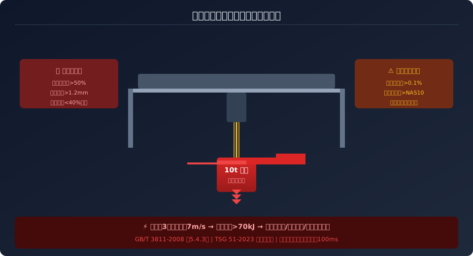
Excessive brake lining wear — This is the most common cause, accounting for approximately 45% of routine faults. During every lowering operation, the hoisting mechanism's service brake must convert potential energy into frictional heat. When brake lining wear exceeds 50% of the original thickness (per the brake lining wear limit requirements in GB/T 6333), the brake's rated torque drops to 40%–60% of its initial value, making it impossible to stop the load within a safe distance. Typical symptoms: brake clearance increases beyond the allowable limit (normal clearance: 0.5–0.8 mm; out-of-limit: >1.2 mm), accompanied by a sharp squealing noise during braking.
Hydraulic brake fluid contamination or leakage — Hydraulic thruster brakes rely on hydraulic oil to transmit thruster thrust. When the water content in the hydraulic oil exceeds 0.1% or the solid particle contamination level exceeds NAS Class 10, the valve spool may stick in a partially open position, causing the brake to apply only partial torque and the load to "creep" downward slowly. More dangerously, micro-leaks at hydraulic hose joints (<0.1 mL/h) are difficult to detect during routine inspections; once cumulative loss exceeds 50 mL, system pressure drops to the braking threshold. Reference: hydraulic oil cleanliness requirements in JB/T 6406-2006.
Electrical control system malfunction — During lowering, the VFD dissipates regenerative energy through the braking resistor. If the braking unit's IGBT fails or the braking resistor opens, the DC bus voltage can surge to the overvoltage protection threshold (typically 720V DC) within 0.5 seconds. The VFD then blocks its output pulses, the motor loses electromagnetic braking torque, and the load accelerates freely under gravity. Per Clause 5.3 of GB/T 28264-2017 (Safety Monitoring and Management System for Lifting Appliances), which addresses overspeed protection signal acquisition and interlocking, such faults must trigger emergency braking within 200 ms.
Five-Step Emergency Response Procedure
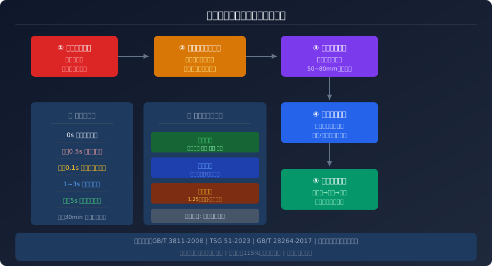
Step 1: Press the Emergency Stop Button Immediately — Cut off the main power to the hoisting mechanism and simultaneously activate the emergency brake (if fitted). The emergency brake is typically a normally-closed spring-applied brake that engages upon power loss, with a response time of <100 ms. Note: even a standard service brake requires 2–3 seconds to build braking force after power-off (due to hydraulic thruster return delay); the emergency brake provides a second line of defense on top of this.
Step 2: Engage the Lowering Limit Interlock — If the load is still moving, the operator should immediately move the master switch to the hoisting position, using the motor's reverse-torque plugging action to assist deceleration. However, this operation has strict limitations: cranes driven by VFDs must not be forcibly reverse-started in a stalled condition (this would trigger IGBT overcurrent protection). This measure applies only to older electrical control systems using wound-rotor asynchronous motors with rotor series resistance speed control.
Step 3: Use the Lowering Limit Switch for Mechanical Buffering — As the load approaches the lower limit position, the heavy hammer limit switch provides approximately 50 mm–80 mm of buffer travel. At this point, at least 3 safety wraps of wire rope must remain on the drum (per the safety wrap requirement in Clause 5.2.1.2 of ISO 4301) to provide additional frictional resistance to assist stopping.
Step 4: Isolate the Hazardous Area — All personnel must immediately evacuate the area beneath the load and the potential falling radius (typically one-third of the lifting height). The site supervisor should use a whistle or two-way radio to broadcast the emergency evacuation signal, and no personnel are permitted to walk beneath the suspended load.
Step 5: Post-Incident Fault Investigation and Documentation — Once the situation is under initial control, organize technicians to investigate the root cause. Recommended investigation sequence: measure brake lining thickness → test hydraulic system pressure → inspect the braking unit in the electrical control cabinet → read fault codes from the VFD. Per the requirements of TSG Q7015-2016 (Periodic Inspection Rules for Lifting Appliances), all emergency braking events must be documented in detail in the equipment file, including time of occurrence, load tonnage, corrective actions taken, and repair solutions.
The diagram below outlines the complete emergency response path from fault detection to investigation completion:
Preventive Maintenance and Tiered Inspection Schedule
Preventing uncontrolled load lowering hinges on a tiered inspection system with progressively deeper checks at each interval:
Daily inspection — Check brake clearance (using a feeler gauge; normal: 0.5–0.8 mm; adjust if exceeding 1.0 mm) and hydraulic oil level (must not be below the 1/3 mark on the gauge). Visually confirm no visible broken wires on the wire rope.
Weekly inspection — Measure brake lining thickness and record the wear curve. If the wear rate exceeds 0.1 mm/month, schedule replacement in advance to avoid unplanned downtime.
Monthly inspection — Perform a lowering brake test at rated load and measure the braking distance. Per ISO 4301, at 1.25 times the rated load, the braking distance must not exceed 1/100 of the rated lifting speed (e.g., for a lifting speed of 1 m/s, the braking distance must not exceed 10 mm).
Quarterly inspection — Conduct a full-load emergency braking drill to verify that braking distance meets standard requirements. Also calibrate the overspeed switch trip point (115% ± 5% of rated speed) and check the emergency brake response time.
Key Parameters and Standard Requirements
| Inspection Item | Standard Requirement | Detection Method | Abnormal Handling |
|---|---|---|---|
| Brake Friction lining Thickness | >=50% of Original Thickness | Vernier caliper/Ultrasonic Thickness Measurement | Wear Replace Immediately if Exceeding Limit |
| Brake Clearance | 0.5~0.8mm | Feeler Gauge Measurement | Exceeding1.0mm Adjust Immediately |
| Hydraulic Oil Cleanliness | <=NAS Class 10 | Particle Counter/Oil Sampling | Replace Oil Immediately if Exceeding Standard |
| Braking Resistor Resistance Value | Nominal Value±10% | Digital multimeter | Deviation>10%Replace Immediately if Exceeding Limit |
| Overspeed Switch Trip Value | 115% of Rated Speed | Tachometer/VFD Monitoring | Deviation>5%Re-Calibration |
| emergency brake Response time | <=200ms | oscilloscope/High-Speed Camera | Check Solenoid Valve if Exceeding Time |
Crane Brake Safety: Prohibited Actions and Mandatory Requirements
Strictly Prohibited — Adjusting brake clearance while the hoisting mechanism is in operation. Brake adjustments may only be performed after the power supply has been completely disconnected and the load has been confirmed to be resting safely on the ground.
Strictly Prohibited — Reversing the direction of travel while the load is accelerating during lowering. This can cause the wire rope to slacken and then suddenly tighten, generating dangerous impact loads on the entire hoisting system.
Mandatory — After replacing hydraulic oil in hydraulic brakes, perform at least three no-load braking tests to fully purge air from the hydraulic lines and verify that brake clearance meets specification.
Mandatory — VFD-driven systems must be equipped with braking resistor overheat protection (temperature switch opens at >180°C) to prevent fire hazards when regenerative braking energy cannot be dissipated.
Safety Warning
If the main hook begins to lower out of control, never position personnel beneath the suspended load to attempt manual braking, and never reverse the travel direction while the load is accelerating downward (this may cause the wire rope to slacken and suddenly re-tension, creating severe impact loads). The correct first response is always to press the Emergency Stop Button and evacuate the hazardous area immediately. Incident case analysis shows that within the critical 3-second response window during a lowering malfunction, correct operator action can reduce equipment damage by more than 70%.
Frequently Asked Questions About Crane Brake Maintenance
Q: At what wear level must brake friction linings be replaced? Is there a quantitative standard?
A: Per GB/T 6333, friction linings must be replaced when wear exceeds 50% of the original thickness. For electromagnetic brakes, replacement is also required when brake clearance exceeds 1.2mm (standard range: 0.5–0.8mm) and cannot be restored to specification through adjustment. We recommend measuring friction lining thickness monthly with an optical flat and plotting a wear trend curve. If the wear rate suddenly accelerates (exceeding twice the normal rate), schedule replacement at the next scheduled downtime.
Q: How often should hydraulic brake fluid be changed, and what grade of hydraulic oil should be used?
A: Hydraulic brakes should use L-HM 46 anti-wear hydraulic oil (ISO VG 46), with an oil change interval of every 2,000 operating hours or once per year, whichever comes first. In high-temperature workshops (ambient temperature >40°C) or dusty environments, the interval should be shortened to 1,000 hours. After each oil change, the system must be purged: start the oil pump and cycle the push rod at least 10 times to confirm that push rod travel and brake clearance return to standard values. Reference JB/T 6406-2006 for detailed procedures.
Q: Why can't the motor be reversed to brake when a VFD-driven crane experiences uncontrolled lowering?
A: When the VFD detects that the motor is being driven externally at high rotational speed, the actual rotor speed far exceeds synchronous speed, and the back-EMF generated in the stator windings can exceed the DC bus voltage. If a reverse start command is forced under these conditions, the IGBT modules will experience instantaneous currents 3–5 times their rated value, triggering overcurrent protection trip (OC fault) and causing the motor to lose all electromagnetic braking torque. Therefore, VFD-driven cranes must rely on a braking resistor and braking unit to dissipate regenerative energy as heat, or be equipped with an independent emergency mechanical brake.
Q: How can routine inspections quickly identify potential uncontrolled lowering risks in the braking system?
A: Use the "three visual checks and one auditory check" method. Visual checks: (1) brake clearance — use a feeler gauge to verify it does not exceed 1.0mm; (2) friction lining condition — normal color is gray-brown, blue discoloration indicates overheating, and cracking indicates aging; (3) hydraulic oil level — top up if below the 1/3 mark on the sight glass. Auditory check: listen during braking — a uniform low-friction sound is normal, while a sharp squeal indicates severely worn or carbonized friction linings. Additionally, perform a no-load hoist/lower cycle before each lift — if you notice a distinct "slipping feel" during braking or braking force takes >0.5 seconds to engage, schedule a detailed inspection immediately.
Kelude Heavy Industry's bridge cranes come standard with a Dual Braking System — a service brake (electromagnetic or hydraulic) plus an emergency brake (normally closed spring-applied type) — meeting the mandatory redundancy requirements for hoisting mechanisms under TSG 51-2023 Crane Safety Technical Supervision Regulation and ISO 4301 Crane Design Standard. We also offer an optional brake condition monitoring module that collects real-time data on brake clearance, friction lining temperature, hydraulic pressure, and other critical parameters, enabling early warning of uncontrolled lowering risks through the CMS system. For more information, visit Crane CMS Condition Monitoring and Remote Operation & Maintenance Solutions.
