

Why Multi-Sensor Fusion in Cranes Starts with Clock Synchronization
📋 Key Summary
In crane intelligent retrofits, multiple sensors—vibration, current, temperature, encoder, and vision—each acquire data independently and stamp their own timestamps. Without clock synchronization first, a vibration spike and a current surge occurring at the same instant get misaligned across different time points, causing fusion algorithms to misinterpret "simultaneous" events as "sequential" ones. The result ranges from feature misalignment to false alarms and missed alarms. Clock synchronization is not a nice-to-have; it is the foundation of multi-sensor fusion. Kelude consistently lists clock alignment as the first acceptance checkpoint before fusion in its retrofit projects. This article breaks down deployment steps and common pitfalls across three dimensions—synchronization accuracy, clock drift, and time-sync protocols—and provides actionable acceptance methods.
Anyone retrofitting sensors onto a crane tends to assume the same thing: as long as data reaches the server, it is ready for model analysis. That assumption holds up in the single-sensor era, but falls apart completely once you move to multi-sensor fusion.
Here is the counterintuitive part: the first hurdle in multi-sensor fusion is rarely the sophistication of the algorithm—it is that timestamps from different data streams simply do not line up. On the same gearbox, the vibration sensor keeps time with its own onboard crystal oscillator, the current transformer samples on the PLC's scan cycle, and the encoder follows the VFD's sampling cadence. Three independent "clocks" drift apart by tens of milliseconds within a minute, and by several seconds over the course of a day.
When a spike in the vibration waveform and a step change in the current waveform get timestamps 50 ms apart, the fusion model infers a false causal sequence—"vibration first, then current"—when in reality the order is reversed. Aligning all sensor timelines to a single reference frame must come before feature extraction and fusion modeling. That is the correct sequence.
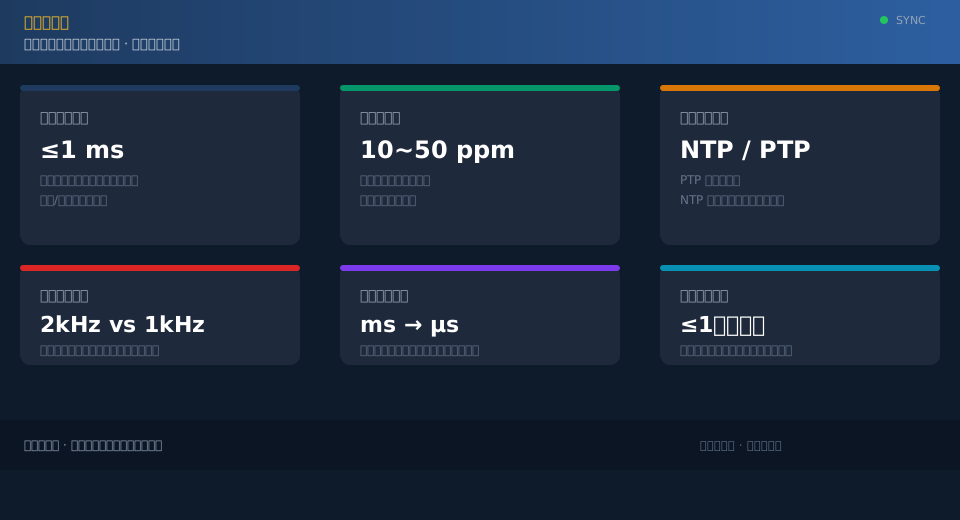
Four Prerequisites for Clock Synchronization: Sensor Inventory, Sampling Rate, Timestamp Source, and Time Reference
Before touching time sync, conduct a thorough sensor inventory. Miss a single channel here, and you will end up with a "straggler"—a sensor that stays outside the sync framework until fusion reveals its data is misaligned.
The core of the inventory is annotating three attributes for each acquisition point: sampling rate, timestamp source, and external trigger support. Vibration sensors typically sample at high rates, with timestamps generated by the acquisition card's local oscillator. Current transformers sample in step with the PLC scan. Encoder timing comes from the VFD, whose cadence relates to the drive sampling mechanism described in GB/T 12668, the Variable Frequency Speed Control Technical Specification. The three timestamp sources are fundamentally different.
Selecting the time reference is equally critical. The entire system needs a "master clock" as the single time origin, with all other devices aligning to it. This reference can be GPS/BeiDou timing, a PTP grandmaster clock, or an existing NTP server on site—depending on the accuracy requirements of the application.
Time-sync requirements are not arbitrary. The basic requirements for parameter acquisition and stored time stamps in GB/T 28264, Safety Monitoring and Management System for Lifting Appliances implicitly mandate consistency in data timing, and multi-sensor fusion can use that as a baseline and tighten further. Kelude's approach in retrofit projects is to first produce a sensor point map listing every channel's sampling rate and timestamp source, then determine which channels need hardware time-stamping and which can be handled in software. The more thorough the inventory, the less rework later.
Tools and Equipment Checklist for Clock Synchronization Deployment
| Equipment/Tools | Application | key parameters | selection recommendations | precautions |
|---|---|---|---|---|
| GPS/BeiDou Time SynchronizationModule | Provide Absolute Time Reference | BeiDou Time SynchronizationAccuracy≤1μs | Open Rooftop Areainstallation、Sky Visibility | Satellite Signal Loss Possible in Severe Weather |
| PTPMaster Clock(Grandmaster) | Distribute Time Reference Across Network | TimestampResolutionNanosecond-Level | SupportIEEE 1588Protocol | System-Wide Unique Master Clock |
| SupportPTPIndustrialnetwork switch | Transparent TransmissionSynchronizationMessage | Support Boundary Clock/Transparent Clock | Reduce Forwarding Jitter | Standardnetwork switchlatencyUnstable |
| Hardware Timestamp Capture Card | HighAccuracyData Tagging | Data TaggingAccuracy≤1μs | Forvibration/Encoder/Camera | Same Reference as Master Clock |
| synchronization accuracyTestingInstrument | AcceptanceverificationAlignmentDeviation | Measurement AlignmentDeviation | factoryAlreadyCalibration | Periodic Recalibration |
How to Set Synchronization Accuracy Parameters: Millisecond vs. Microsecond Alignment Depends on the Fusion Task
Many projects start by asking, "Can you achieve nanosecond-level synchronization?"—without specifying what accuracy they actually need. Higher synchronization accuracy isn't always better; the real question is what temporal resolution the fusion task demands. Every order-of-magnitude improvement in accuracy doubles both cost and complexity.
The deciding factor is straightforward: what is the minimum time difference your fusion algorithm needs to resolve? For vibration-to-current correlation analysis, where events unfold on a millisecond timescale, millisecond-level alignment is sufficient. For multi-channel image and encoder spatial localization fusion, where microsecond-level event ordering must be reconstructed, microsecond-level synchronization becomes necessary.
A practical benchmark is the sampling period. As long as alignment error across all data channels stays below one sampling period, no perceptible misalignment will occur during fusion. Beyond one sampling period, misalignment becomes visible at the feature level. Kelude typically sets the acceptance threshold at "alignment error no greater than half the shortest sampling period" for project delivery.
Deploying Clock Synchronization Step by Step: From Reference Source Selection to Per-Channel Correction
Clock synchronization deployment can be broken down into four sequential steps, each with a clearly defined deliverable.
Step 1: Select and install the master clock. Deploy a GPS/BeiDou timing module or PTP master clock on the factory building roof or in the control room. First verify that it can reliably lock onto the time reference—this is the foundation for all subsequent alignment.
Step 2: Establish the time synchronization access system. Use network switches that support PTP or NTP to connect the master clock to each data acquisition gateway. Verify unit by unit that each device receives time-sync messages, keeping network forwarding jitter as low as possible. At the IoT interface level, refer to the data transmission conventions defined in ISO 24619, the IoT interface specification for cranes.
Step 3: Per-channel time calibration and time stamping. For high-accuracy channels such as vibration, encoders, and cameras, configure hardware time stamping so data carries an accurate timestamp at the moment of acquisition. For slow variables like temperature, where accuracy requirements are lower, software-based time synchronization is sufficient.
Step 4: Perform an end-to-end alignment acceptance test. Inject a known standard test signal into all channels simultaneously, compare timestamps across channels, and confirm that alignment deviation falls within the acceptance threshold. Only then is synchronization considered complete.
End-to-End Clock Synchronization Acceptance Standard
| AcceptanceItem | acceptance criteria/threshold | test method | assessment conclusion |
|---|---|---|---|
| End-to-Endsynchronization accuracy | Fusion Link AlignmentDeviation≤1ms | StandardTestingSignal Injected into All Channels Simultaneously,Compare Timestamps | Qualified |
| 24hClock Drift | Drift After Disconnecting Time Source≤Half of Minimum Sampling Period | Continuous Recording After Disconnecting Master Clock24h | Qualified |
| TimestampResolution | Meet Fusion RequirementsminimumGranularity(μsOrms) | Read EachSensorTimestamp Field Bit Width | Qualified |
| Loss-of-Sync Alarm | After Loss of Sync3sReport Alarm Within | Manually Disconnect Master Clock to Observe Alarm | Qualified |
| Sampling Phase Alignment | Stable Phase Difference Across Sampling Edges | Compare Sampling Edges with Logic Analyzer | Qualified |
| Recovery After Power Cycle | After Restart5minRecover WithinSynchronization | Power Cycle Timing Observation | Qualified |
Three Most Common Clock Synchronization Mistakes: Time-Only Calibration, Ignoring Sampling Phase Offset, and Mixing Time Bases
Most clock synchronization pitfalls aren't in the protocol itself, but in a few engineering details on site. Kelude has identified three high-frequency error categories during project reviews.
The first mistake is calibrating time only without correcting drift. Many assume that once a device has been synchronized, it stays synchronized. In reality, crystal oscillators drift continuously — errors accumulate every minute after synchronization. You must set a periodic re-synchronization interval and trigger an alarm when synchronization is lost.
The second mistake is ignoring sampling phase offset. Even if timestamps on two data streams are accurate, waveforms at the same moment will still be misaligned if the sampling edges themselves don't line up. This is especially critical to check between high-speed vibration and line-frequency current signals — verify that the sampling phase remains stable.
The third mistake is mixing time bases. Some devices sync to GPS time, others to the server's local time, and still others follow the PLC's millisecond counter — these three references have inherent deviations between them, so any alignment effort is wasted. The entire system must be unified to a single time origin.
📖 Related reading:Equipment Health Management (PHM): Big Data and ML-Driven Predictive Maintenance for Overhead Cranes | Visual SLAM Environment Mapping and Positioning for Overhead Cranes
FAQ
Q: Is there a standard defining accuracy requirements for multi-sensor clock synchronization on cranes?
A: Currently, clock synchronization is not a standalone mandatory clause in crane-specific standards, but time-alignment requirements are implied in the basic requirements of GB/T 28264 Safety Monitoring and Management System for parameter acquisition and storage timestamps. In industrial practice, you can follow the general time synchronization approach used in industrial Ethernet and set your own acceptance threshold targeting millisecond or microsecond accuracy. The final criterion should be based on actual operating conditions and fusion task needs — there's no need to pursue accuracy far beyond what the application requires.
Q: What time-synchronization equipment should I buy for multi-source fusion on a crane, and how do I choose between PTP and NTP?
A: For correlation analysis at the millisecond scale — vibration, current, temperature — NTP synchronization is generally sufficient and is the lowest-cost option. For fusion involving multiple image streams, encoder positioning, or other applications that require microsecond-level sequencing, you'll need a PTP grandmaster clock with hardware timestamping. The key to selection isn't buying the most expensive gear — it's first calculating the minimum time resolution your fusion task needs to distinguish, then working backward to determine the required synchronization accuracy.
Q: How can I tell if on-site sensor data isn't aligned? What signals indicate timestamp corruption?
A: Watch for three telltale signs. First, the same event appears with a noticeable time offset across different channels — for example, a vibration spike arriving tens of milliseconds after a current transient. Second, false alarms and missed alarms from the fusion model actually increase after retrofitting new sensors. Third, system times recorded by different devices don't match up — each one tells a different story. If any of these appear, go back and audit the timestamp sources and synchronization status on every channel.
Q: Why do encoder and vibration sensor times drift further and further apart?
A: Every sensor's internal crystal oscillator has a slight frequency error, typically specified in ppm — 10 ppm means the clock may gain or lose 10 microseconds per second. This error accumulates over time: tens of milliseconds per hour, seconds per day. Encoders and vibration acquisition boards use different crystal oscillators that drift independently, so even if they were synchronized initially, their times will diverge increasingly. Periodic re-synchronization is essential.
Clock synchronization is the most overlooked yetMost Failure-Prone Aspect in multi-source fusion on cranes. Aligning the time axes of all sensors first, before diving into feature engineering and model training, is the proven sequence Kelude has validated across multiple projects. Rather than troubleshooting chaotic fusion results after the fact, it's far better to calibrate this "time ruler" from the start.
