

Interpretation of the GB/T 30024 Standard “Verification of the Load-Carrying Capacity of Steel Structures for Cranes”
📌GB/T 30024 "Verification of the Load-Bearing Capacity of Steel Structures for Cranes"It is an important technical specification in the crane industry. This standard, developed by the National Standards Committee, specifies methods for verifying the load-bearing capacity of steel structures in cranes.
This standard provides a unified technical basis for designers, inspection agencies, and users. Krude Heavy Industry strictly adheres to the technical requirements of this standard throughout the product development and manufacturing processes.
Scope and Purpose of the Standard
GB/T 30024, “Verification of the Load-Carrying Capacity of Crane Steel Structures,” primarily specifies the technical requirements and safety criteria related to crane steel structures and applies to all types of lifting machinery with a rated lifting capacity of 0.5 metric tons or more. This standard not only covers the design and manufacturing of new equipment but also provides clear technical guidance for the inspection, maintenance, and retrofitting of in-service equipment. As a key component of the crane standards system, this standard is harmonized with standards such as the EN 13001 series and ISO 4309, collectively forming a comprehensive system of technical specifications. The technical parameters and safety factor requirements specified in the standard provide designers with a clear basis for design and offer quantifiable criteria for type testing and factory acceptance inspections conducted by third-party inspection agencies.
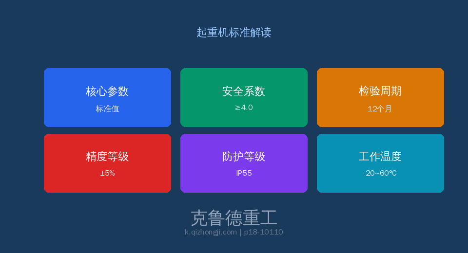
Core Technical Specifications
According to the technical specifications of GB/T 30024, the design and manufacture of load-bearing steel structures for cranes must meet a series of strict technical parameter requirements. These parameters are determined based on extensive experimental data and safety engineering theory, covering the entire process from material selection to structural design. The range of safety factors specified in the standard fully accounts for the fatigue life and ultimate load conditions of lifting machinery under severe operating conditions. In engineering practice, designers must translate the standard’s requirements into specific design parameters to ensure that the load-bearing capacity of each component meets safety requirements.
Comparative Analysis of Key Technical Parameters
| Project | Technical Requirements | Note |
|---|---|---|
| Verification Methods | Allowable Stress Method (Principle)/Limit State Method | Both the ISO and FEM methods are acceptable |
| Safety Factor | ≥1.5 (yield strength)/≥2.0 (ultimate strength) | Dynamic load factor: 1.1–1.4 |
| Load Combinations | Base (Self-Weight + Lift) + 964e98 (Wind) + 629e (Impact) | Find the maximum stress in the envelope |
| Deflection | Full load ≤ L/800, lateral deflection ≤ L/2000 | Unloaded camber ≥ L/1500 |
| First Labor | Class A6 and above must undergo | Welding Details FAT80–100 |
| Stability | Global Overturning Stability + Local Buckling of the Web | The design of the additional reinforcement meets the requirements. |
Inspection Requirements and Frequency
GB/T 30024 sets forth clear requirements for factory inspections, type testing, and periodic inspections of crane steel structures. Factory inspections shall be conducted unit by unit by the quality inspection department at the manufacturer’s plant; equipment that passes inspection shall be accompanied by a detailed inspection report and a certificate of conformity. Type testing shall be conducted when a new product is first put into production, when production is transferred to a different facility, or when major structural changes are made. The periodic inspection interval for in-service equipment is determined based on the duty class and operating environment, and generally shall not exceed 12 months. For heavy-duty cranes operating continuously at duty classes A7 through A8, the inspection interval shall be appropriately shortened to 6 months.
| Project | Technical Requirements | Note |
|---|---|---|
| Structural Strength | Main Beam Stress Test | Year + Density When Overloaded |
| Deflection | Level Surveying | Annual + ≤ L/800 |
| Weld | UT/MT Inspection | A6+ Annual / A6- Annual |
| Stability | Reinforcement Inspection | Year + Deformation/Fracture |
Safety Operation and Management Requirements
Safety operations and daily management play a crucial role in the implementation of GB/T 30024. The standard places particular emphasis on the importance of operator qualifications and training, requiring that all operators undergo specialized training and obtain the appropriate qualifications before being allowed to work. Equipment-using entities should establish a comprehensive equipment record management system to document in detail the entire process of installation, use, maintenance, and inspection. Any identified safety hazards must be addressed in accordance with the corrective action procedures specified in the standard to ensure that the equipment remains in a safe and controllable condition at all times. In addition, the standard sets forth restrictive requirements regarding the use of equipment under extreme operating conditions.
Frequently Asked Questions
Q: What are the verification methods specified in GB/T 30024?
Answer: The allowable stress method is primarily used; the limit state method may also be referenced. The safety factor is ≥1.5/≥2.0.
Q: How should load combinations be considered?
Answer: Basic + Additional (Wind) + Special (Impact). Dynamic load factor: 1.1–1.4. Take the maximum value of the envelope.
Q: When is labor verification required?
Answer: Required for Grade A6 and above. Welding detail classification: FAT 80–100.
Q: What are the key components of the annual inspection?
Answer: Measure the deflection of the main beam (≤ L/800), perform UT testing on the welds, and verify stability.
🔧 Krude Heavy Industry — Specializing in crane design and manufacturing, with products strictly compliant with the GB/T 30024 standard system.
