

GB/T 6067.1 Crane Safety: 5 Protective Devices and 7 Checks
GB/T 6067.1-2010, "Safety Rules for Lifting Appliances – Part 1: General Requirements," is the foundational mandatory standard for crane safety in China, covering the full lifecycle safety requirements from design, manufacturing, installation, retrofitting, maintenance, and use to inspection. This standard specifies the configuration principles and performance indicators for five categories of safety protection devices, along with seven key parameters for periodic inspection. This article outlines the core provisions of the standard, integrating the latest requirements of TSG 51-2023, to provide crane users with a practical guide for equipment selection and compliance.
GB/T 6067.1-2010 serves as the "master safety standard" for the crane industry. The design and manufacturing of all equipment—including bridge cranes, gantry cranes, tower cranes, mobile cranes, portal cranes, and electric hoists—must comply with its general safety provisions. The standard establishes a safety framework across three dimensions: personnel protection, equipment protection, and environmental protection. Among its chapters, Chapter 9, "Safety Protection Devices," and Chapter 12, "Inspection and Testing," are the two most frequently referenced sections in daily operations and maintenance. The following analysis is structured around these two main themes: the five device categories and the seven inspection parameters.
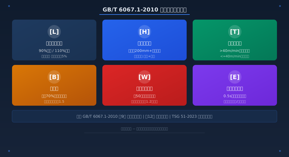
Which Safety Protection Devices Are Mandatory Under GB/T 6067.1?
Chapter 9 of GB/T 6067.1 classifies safety protection devices into five main categories, each addressing different protection targets and failure consequences. The following breakdown examines each category, ordered from highest to lowest risk level.
Category 1: Load Limiters and Load Moment Limiters
Clause 9.2 mandates that cranes with a rated lifting capacity greater than 1t must be equipped with a load limiter. An audible and visual pre-warning signal is required when the load reaches 90% of the rated capacity, and the hoisting power source must be automatically cut off at 110% of the rated capacity. Kelude's bridge cranes come standard with a digital load limiter offering a comprehensive accuracy of ±3% and a response time of ≤200ms, exceeding the standard's requirement for a "comprehensive error not exceeding ±5%."
Mobile cranes have an additional requirement for a load moment limiter (LML). Clause 9.3 stipulates that a pre-warning must be triggered at 90% of the rated moment, with automatic stoppage of dangerous movements between 100% and 110% of the rated moment. GB/T 3811-2008 "Crane Design Standard" provides the design basis for setting LML thresholds through its specifications on load combinations and safety factors.
Category 2: Travel Limit Switches
Clauses 9.4 through 9.7 specify the technical requirements for three types of limit devices: the hoisting height limit switch, the load-lowering height limiter, and the travel limit switch.
Hoisting Height Limit Switch (Clause 9.4): The hook must automatically stop and hold its position when it reaches a point ≥200mm from the uppermost limit. Kelude employs a two-stage limit design—a primary deceleration limit switch (activated 500mm from the upper limit) and a secondary power-disconnect limit switch (activated 200mm from the upper limit). This dual-redundancy approach aligns with the mandatory "double limit" requirement of TSG 51-2023 Crane Safety Technical Supervision Regulation.
Load-Lowering Height Limiter (Clause 9.5): The hoisting mechanism must automatically stop when fewer than two wraps of wire rope remain on the drum, preventing rope reverse winding and potential load drops.
Travel Limit Switch (Clause 9.6): The crane bridge and trolley travel mechanisms must automatically stop at a distance ≥200mm from the end of the crane rail, with buffers simultaneously absorbing residual kinetic energy. The standard specifies that cranes with a travel speed ≤40m/min may be equipped with a single end-stop limit switch, while those exceeding 40m/min must have a two-stage limit system incorporating both deceleration and final stop functions.
Category 3: Buffers and Buffer Stops
Clause 9.8 requires that both the crane bridge and trolley travel mechanisms on rail-mounted cranes be fitted with buffers at their extremities, and that buffer stops be installed at the ends of the crane rail. Buffers must be capable of absorbing the full kinetic energy generated by an impact at 70% of the rated load at rated speed without undergoing plastic deformation. Reference for buffer selection and design parameters can be found in GB/T 32071-2017 "Crane Buffers."
Kelude's standard configuration utilizes polyurethane buffers for cranes with a rated capacity of ≤20t and hydraulic buffers for those exceeding 20t. Buffer capacity is calculated using the kinetic energy formula E=mv²/2, applying a 1.5 safety factor, fully satisfying the standard's requirements.
Category 4: Wind Protection and Anti-Slip Devices
Clause 9.9 mandates that outdoor rail-mounted cranes be equipped with wind protection and anti-slip devices, including rail clamps, anchor devices, and wheel chocks. These systems must be designed to withstand wind loads corresponding to the maximum wind speed expected once every 50 years in the local area. Kelude equips its outdoor gantry cranes with a dual wind protection system comprising an electric rail clamp and a manual anchor device, with a clamping force ≥1.2 times the sliding force generated by the maximum design wind load.
Category 5: Interlock Protection and Emergency Stop
Clause 9.12 requires that an emergency stop switch be provided at all control positions. Activation must cut off the main power supply and prevent automatic reset. Kelude installs independent emergency stop buttons in the operator cab, on the floor control grip, and on the remote control of every crane. This three-level series-connected emergency stop circuit ensures that power can be immediately cut from any location.
Clause 9.13 further specifies door and hatch cover interlocks: when the operator cab door, end carriage guardrail door, or maintenance hatch cover is open, the crane's travel mechanisms must be automatically de-energized to prevent personnel from being injured while working near moving parts.
What Are the 7 Key Periodic Inspection Criteria and Acceptance Limits?
Chapter 12, "Inspection and Testing," of GB/T 6067.1 categorizes crane inspections into three types: initial inspection, periodic inspection, and special inspection. Periodic inspections are required every 2 years and cover seven major systems. The key parameters and acceptance criteria for each are detailed below.
Inspection procedures also reference the supervision inspection rules of TSG 51-2023: newly installed cranes must pass a supervision inspection before being put into service, and cranes in use must undergo periodic inspection every 2 years. Kelude provides comprehensive technical support from pre-delivery inspection to on-site periodic inspection, ensuring all equipment operates in a timely and compliant manner.
Inspection Item 1: Metal Structure Check (Clause 12.3.1)
Main Girder Mid-span Camber: For bridge cranes, the camber should be (0.9~1.4)S/1000 (where S is the span). For gantry cranes, the cantilever end should have an upward deflection of (0.9~1.4)L/350 (where L is the cantilever length).
Main Girder Web Plate Flatness: The allowable wave height is ≤0.7δ (δ = plate thickness) in the compression zone and ≤1.2δ in the tension zone. If the main girder deflection exceeds S/2000, repair or load reduction is mandatory.
Inspection Item 2: Wire Rope Inspection (Clause 12.3.2)
A wire rope must be discarded when the number of visible broken wires in one lay length reaches 10% of the total number of wires in the rope. A diameter reduction of ≥7% relative to the nominal diameter also mandates replacement. Any single defect—such as kinking, crushing, electric arc damage, or core exposure—results in immediate discard, regardless of the broken wire count.
Inspection Item 3: Hook Inspection (Clause 12.3.3)
A hook must be discarded if the opening deformation exceeds 15% of its original size, if torsional deformation exceeds 10°, or if corrosion on the hook shank exceeds 10% of the original dimension. For laminated hooks, replacement is required if rivets are loose or if bushing wear exceeds 50% of the original thickness.
Inspection Item 4: Brake Inspection (Clause 12.3.4)
Brake friction linings must be replaced when wear exceeds 50% of the original thickness. The brake wheel surface must be repaired or replaced if wear reaches ≥1.5mm (for wheel diameters ≤300mm) or ≥2.0mm (for diameters >300mm). Brake slippage is checked by suspending the rated load for 1 minute; the allowable drop distance must not exceed 1/100 of the rated hoisting speed (in mm).
Inspection Item 5: Safety Device Functional Test (Clause 12.3.5)
Load Limiter: Test with 90% and 110% of the rated load. The pre-warning signal must activate at 90%, and the hoisting power source must automatically cut off at 110% for a pass. Hoisting Height Limit Switch: The hook must automatically stop and hold when it reaches within 200mm of the upper limit. Travel Limit Switch: The crane bridge or trolley must automatically stop when it reaches within 200mm of the rail end.
Inspection Item 6: Electrical System Inspection (Clause 12.3.6)
Insulation Resistance: Main circuit ≥0.5MΩ (measured with a 500V megohmmeter), control circuit ≥0.5MΩ. Grounding Resistance: ≤4Ω for TN systems, ≤10Ω for TT systems. Emergency Stop Button Test: The test is considered passed if the total power supply is completely cut off within 0.5s of pressing the button.
Inspection Item 7: No-Load and Rated Load Tests (Clause 12.3.7)
No-Load Test: Each mechanism runs through 3 full cycles with no abnormal noise, jamming, or creeping. Rated Load Test: Hoist the rated load through 3 full lifting/lowering cycles, plus full-travel operation of the crane bridge and trolley, to check braking slip, structural deflection, and running smoothness. Dynamic Load Test (at 1.1 times rated load) and Static Load Test (at 1.25 times rated load) are performed during initial inspection and post-retrofit inspection.
Comparison of Key Parameters for 5 Types of Safety Protection Devices
| Device Type | Standard Clause | Critical Parameterand Action Threshold |
|---|---|---|
| Lifting Capacity Limiter / Load Limiter | 9.2Item | 90%Pre-warning / 110%Power Cut-off / Combined error not exceeding ±5% |
| Lifting Height Limit Switch | 9.4Item | Distance from limit position not less than200mm Stop / Two-stage Limit |
| travel limit switch | 9.6Item | Greater than40m/min Shall be two-stage / Not exceeding40m/min End Limit |
| Buffer | 9.8Item | Absorb70%Rated-load Full-speed Kinetic Energy / Safety factor Distance from limit position not less than1.5 |
| Anti-wind and Anti-skid Device | 9.9Item | Resist50Once-in-a-year Wind Speed / Rail Clamping Force Not Less Than1.2Times Wind-load Skidding Force |
| Emergency Stop Switch | 9.12Item | 0.5sCut off power within Power Supply / Non-auto-reset |
Periodic Inspection Criteria: 7-Point Reference Table
| Inspection Item | Inspection Period | Critical Judgment Standard |
|---|---|---|
| Metal Structure | Per2Year | Camber Distance from limit position not less than0.9S/1000 / Deflection Not exceeding S/2000 |
| Wire Rope | Daily Visual Inspection+Per2Annual Full Inspection | Number of broken wires Not exceeding10%Total Wire Count / Diameter reduction Not exceeding7% |
| Hook | Per2Year | Opening Increase Not Exceeding15% / Torsion Not Exceeding10Degree |
| Brake | Per2Year | Friction lining Wear Not exceeding50% / Sliding Down Not Exceeding V/100 |
| Safety Device | Per2Yearfunctional test | 90%Pre-warning Normal / 110%Cut-off Normal |
| electrical system | Per2Year | Insulation Resistance Distance from limit position not less than0.5Megaohm (MΩ) / Grounding Resistance Not exceeding4Megaohm (MΩ) |
| Load test | First+Retrofit After | 1.1Timesdynamic load3Cycle / 1.25Timesstatic load10min No Plasticity Deformation |
90%
Load Limiter pre-warning threshold — audible and visual alarm triggered when the load reaches 90% of the rated lifting capacity.
200mm
Limit switch stopping distance — the hook, crane bridge, or trolley automatically stops 200 mm before reaching the end limit position.
2Turn(s)
Drum safety margin — the limit switch is activated when fewer than 2 wraps of wire rope remain on the drum.
10%
Wire rope discard criteria — the rope must be replaced when the number of broken wires in one rope lay exceeds 10% of the total wire count.
15%
Hook opening discard limit — the hook must be scrapped if deformation exceeds 15% of its original dimension.
0.5M
Minimum electrical insulation requirement — insulation resistance of the main and control circuits must not be less than 0.5 MΩ.
Crane Safety Device Installation Positions and Trigger Logic
During installation and commissioning, users often lack a clear spatial understanding of where safety devices are placed and how they interact. Using a typical overhead crane as an example, here is a breakdown of the mounting locations and operating ranges for five key safety devices.
The Load Limiter is mounted on the drum support or the equalizer sheave shaft, using strain-gauge sensors to measure wire rope tension. Kelude uses a pin-type sensor that directly replaces the equalizer sheave shaft, achieving an installation accuracy of ±0.5% FS and eliminating the need for additional structural modifications. For mobile cranes, the Load Moment Limiter (LML) is used, with sensors installed on the luffing cylinder or at the boom base.
The Hoisting Height Limit Switch is mounted at the drum end or above the hook block sheave. It operates either by counting drum rotations via a rotary limit switch or through direct mechanical contact with a limit switch. Travel limit switches are installed on the crane bridge and trolley end carriages, with corresponding trip dogs placed at both ends of the crane rail.
Buffers are mounted on both sides of the crane end carriages and at both ends of the trolley frame, aligned with the buffer stops at the rail ends. For outdoor cranes, the wind protection device — a rail clamp — is installed on the non-drive side of the bridge travel mechanism. The anchor device is mounted at the bottom of the crane end carriage, aligning with anchor seats embedded in the ground.
Emergency Stop buttons are located on the operator cab console, the wired pendant, and the wireless remote control. These buttons are wired in series within the main contactor control circuit, so pressing any single one cuts off the main power supply.
GB/T 6067.1 vs. TSG 51-2023: Key Differences in Inspection Requirements
GB/T 6067.1 is a national recommended standard (the 2010 edition's mandatory clauses have been converted to recommended status), while TSG 51-2023 is a mandatory safety technical regulation for special equipment issued by the State Administration for Market Regulation. The core differences in inspection requirements are as follows:
Inspection Frequency: GB/T 6067.1 recommends a periodic inspection every 2 years. TSG 51-2023 mandates a supervisory inspection for newly installed cranes, followed by periodic inspections every 2 years, and additionally requires an annual self-inspection.
Inspection Scope: GB/T 6067.1 covers 7 items: metal structure, wire rope, hook, brake, safety devices, electrical system, and load test. TSG 51-2023 adds two more requirements: acceptance of the Safety Monitoring and Management System (per GB/T 28264-2017) and a safety assessment for cranes in service for more than 15 years.
Handling of Non-Conformities: GB/T 6067.1 stipulates that failed items must be rectified within a specified timeframe and re-inspected. TSG 51-2023 requires immediate shutdown for serious hazards, while general hazards must be rectified within a set deadline. Failure to comply results in penalties under Article 83 of the Special Equipment Safety Law. Kelude recommends that users conduct self-inspections against both standards, using the mandatory requirements of TSG 51-2023 as the baseline and the technical specifications of GB/T 6067.1 as the target performance level.
📖 Related Reading:
• TSG 51-2023 Safety Technical Specification for Special Equipment: Standard Interpretation
• GB/T 5905 Crane Test Procedure: 3 Types of Load Test Procedures and 6 Acceptance Criteria
Common Non-Conformities Found During Periodic Crane Inspections
Based on field inspection data collected by the Kelude after-sales team over the past 3 years, here are the 5 most common non-conformities found during periodic inspections, along with their corresponding corrective actions.
1. Load Limiter Malfunction: Sensor zero-point drift or loose wiring. Solution: Calibrate at least once a year and use spring washers on terminal blocks to prevent loosening.
2. Excessive Brake Slippage: Worn friction linings not replaced in a timely manner. Solution: Maintain a friction lining thickness log and replace them when the remaining thickness falls below 3 mm.
3. Wire Rope Broken Wires Exceeding Limits: Lack of regular visual inspection records. Solution: Implement a 5-point pre-use inspection checklist covering broken wires, wear, corrosion, deformation, and lubrication.
4. Grounding Resistance Exceeds Limits: Corroded or broken grounding wire. Solution: Measure grounding resistance quarterly; replace the grounding electrode if resistance exceeds 4 Ω in a TN system.
5. Travel Limit Switch Failure: Shifted trip dogs or water ingress into the switch. Solution: Conduct monthly functional tests, use limit switches with an IP65 waterproof rating, and weld the trip dogs securely in place.
Frequently Asked Questions
Q: What is the difference between GB/T 6067.1 and TSG 51-2023 regarding safety device requirements?
A: Chapter 9 of GB/T 6067.1 specifies the technical requirements and trigger thresholds for five types of safety devices (e.g., Load Limiter pre-warning at 90% and cut-off at 110% of rated capacity). As a national recommended standard, it provides technical reference parameters. TSG 51-2023 makes these devices subject to mandatory supervisory inspection, stating that cranes cannot be put into service without passing inspection. Violations are penalized under Article 83 of the Special Equipment Safety Law, with fines ranging from approximately $4,400 to $44,400. In short, GB/T 6067.1 defines "how to do it," while TSG 51-2023 mandates that "it must be done."
Q: How to diagnose and fix excessive brake drop on a crane? Acceptance criteria and a 3-step repair guide
A: Per ISO 12480-1, Clause 12.3.4, and ISO 4301, the allowable drop for a rated load held stationary for 1 minute must not exceed 1/100 of the rated hoisting speed (in mm). For example, a crane with a hoisting speed of 8 m/min is acceptable if the load drop does not exceed 80 mm. Three common causes are: ① Worn friction linings (replace when remaining thickness is less than 3 mm or wear exceeds 50% of the original thickness); ② Weakened brake springs (re-adjust to the specified compressed length); ③ Contaminated brake wheel surface (clean with acetone). Kelude recommends keeping a monthly brake drop test log. If a progressive increase is observed over three consecutive months, schedule maintenance proactively to avoid failing periodic inspections.
Q: What types of wind protection and anti-skid devices are used on outdoor cranes, and how do you verify compliance?
A: ISO 12480-1, Clause 9.9, defines three categories of wind protection devices: ① Manual rail clamps — for smaller gantry cranes with a span of 22 m or less; ② Electric rail clamps — for medium-to-large gantry cranes with spans exceeding 22 m, interlocked with an anemometer to automatically engage when wind speed exceeds 20 m/s; ③ Anchor devices (ground anchors with pin-type or automatic locking) — for securing the crane against typhoon-force winds when out of service. Compliance criteria: the clamping force must be no less than 1.2 times the maximum wind-induced skidding force (verified per ISO 4301 load combinations), and the anchor system must withstand the maximum wind speed expected once in 50 years (based on local meteorological data). Kelude provides a wind load calculation report with every outdoor crane, delivered as part of the equipment documentation.
Q: How to troubleshoot and repair crane electrical system insulation resistance below 0.5 megohms?
A: ISO 12480-1, Clause 12.3.6, requires insulation resistance of no less than 0.5 megohms for both main and control circuits, measured with a 500V megohmmeter (insulation tester). If readings fall below this threshold, follow these steps: ① Disconnect all electrical loads (motors, brake coils, contactor coils) and test each section to isolate the low-resistance area; ② Inspect cables for aged or cracked insulation — on outdoor cranes, replace cables older than 5 years as a precaution; ③ Check junction boxes for water ingress — upgrade to IP65 sealing and add drain holes; ④ For moisture-affected motor windings, dry in an oven at 80°C for 24 hours or apply low-voltage DC current to drive out moisture. Kelude cranes come standard with double-insulated cables and IP65-rated junction boxes, significantly reducing the risk of insulation failure.
