

How to Adjust Electric Hoist Brake Gap: Cone, Disc & Electromagnetic
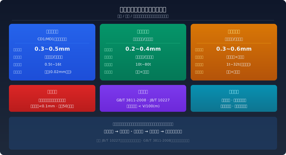
The key to electric hoist brake gap adjustment lies in the clearance standards of three brake types—cone brake: 0.3–0.5 mm (standard on CD1/MD1 models), disc brake: 0.2–0.4 mm (hydraulic type for heavy loads), and electromagnetic brake: 0.3–0.6 mm (VFD hoists). Improper adjustment leading to load slipping or brake drag is the most common cause of electric hoist safety incidents.
The electric hoist brake is the last line of defense for safe hoisting mechanism operation. Per ISO 4301 Crane Design Standard and JB/T 10227-2017 Brake for Electric Hoist, the braking torque must be at least 1.5 times the rated hoisting torque, and the braking descent distance must not exceed 1/100 of the rated lifting speed. In practice, however, over 60% of brake failures on site stem from incorrect gap adjustment—an oversized gap reduces braking force and causes load slipping, while an undersized gap leads to brake drag, overheating, rapid friction lining wear, and even burnout. This article covers the standard clearance values for all three brake types, along with the specific measuring tools, adjustment procedures, and verification methods.
Cone Brake Gap Adjustment (CD1/MD1 Models)
CD1/MD1 wire rope electric hoists come standard with a cone brake integrated into the cone rotor motor—the most common braking arrangement for electric hoists. The cone brake clearance standard is 0.3–0.5 mm (per side), measured with a 0.02 mm precision feeler gauge between the brake cone surface and the brake ring. When the motor is de-energized, the cone rotor moves axially under spring force, pressing the brake cone against the brake ring to generate braking torque. When energized, the rotor moves in the opposite direction under electromagnetic force, overcoming the spring force and releasing the brake.
Step 1—De-energize the hoist and lock out the power supply. Measure the current clearance with a feeler gauge and record the reading.
Step 2—Loosen the lock nut on the brake end cover. Adjust the spring preload—and thus the clearance—by adding or removing adjustment shims (available in 0.1 mm, 0.2 mm, and 0.5 mm thicknesses).
Step 3—Add shims to increase the clearance or remove shims to decrease it. Make adjustments in increments no larger than 0.1 mm, then re-tighten the lock nut.
Step 4—Re-measure the clearance with the feeler gauge to confirm it falls within 0.3–0.5 mm, with no more than 0.1 mm deviation between the two sides.
Key considerations: The brake ring on a cone brake is a wear part with a typical service life of 1,000–2,000 hours. After installing a new brake ring, run 50 break-in cycles (25 empty lifts and 25 empty lowerings) before re-measuring the clearance, as the brake ring surface undergoes slight plastic deformation during break-in. Replace the brake ring when its thickness wears down to less than 50% of the original—otherwise, even a clearance within the standard range cannot guarantee sufficient braking torque.
Disc Brake Gap Adjustment (Hydraulic/Electromagnetic Types)
Disc brakes are used on heavy-capacity electric hoists (10 t and above) and metallurgical electric hoists, driven by either a hydraulic thruster or an electromagnet. The clearance standard for disc brakes is tighter than for cone brakes—0.2–0.4 mm—measured with a feeler gauge and a dial indicator. A disc brake consists of a brake disc, friction linings, clamping springs, and a thruster. During operation, the thruster overcomes the spring force to pull the friction linings away from both sides of the brake disc.
Adjustment is made by turning the adjusting screw on the brake housing—turn clockwise to reduce the clearance, counterclockwise to increase it. Each quarter-turn changes the clearance by approximately 0.05–0.08 mm. When adjusting, measure the gap on both the upper and lower linings simultaneously to ensure even clearance on both sides. For hydraulic thruster types, also check the hydraulic oil level and condition—use No. 10 aviation hydraulic oil, and replace it if the water content exceeds 0.1% or if particulate contamination is detected. If the load slipping distance exceeds 50 mm (under no load) after braking, the linings need adjustment or replacement.
A common issue unique to disc brakes is delayed closure caused by slow thruster oil return. When the thruster return time exceeds 0.5 seconds, the brake response becomes sluggish. Troubleshooting checklist: abnormal hydraulic oil viscosity (use No. 46 in summer, No. 32 in winter), blocked oil return line, or a stuck push rod. After repair, perform three no-load braking tests to purge air from the hydraulic lines.
Electromagnetic Brake Gap Adjustment (VFD Hoists/Spring-Applied Types)
Electromagnetic brakes (spring-applied, power-off brakes) are widely used in VFD-controlled electric hoists. Their operating principle: when energized, the electromagnetic coil generates magnetic force that overcomes the spring force, pulling in the armature to release the brake disc; when de-energized, the spring force pushes the armature against the brake disc to apply the brake. The clearance standard for electromagnetic brakes is 0.3–0.6 mm, controlled by adjusting the armature stroke via the adjusting bolt.
Before adjusting, use a multimeter to measure the DC resistance of the electromagnetic coil (typically 80–200 Ω) and the rectifier output voltage (DC 170–200 V) to confirm the electrical system is functioning properly. Then loosen the anti-loosening nut and turn the adjusting bolt—clockwise to decrease the clearance, counterclockwise to increase it. After adjustment, measure the gap at four evenly spaced points around the brake disc circumference with a feeler gauge; the deviation between the four points must not exceed 0.05 mm. Finally, use a torque wrench to tighten the anti-loosening nut to the specified torque.
The most common electromagnetic brake failure is coil burnout, which prevents the brake from releasing. The motor will stall and emit a humming sound; if power is not cut promptly, the motor windings can burn out within minutes. Preventive action: regularly measure coil resistance to track insulation aging trends, and replace the coil assembly when insulation resistance drops below 0.5 MΩ.
Brake Clearance Comparison Table for All Three Types
| Parameter | Cone brake | Disc Brake | Electromagnetic brake |
|---|---|---|---|
| Standard Release Distance | 0.3~0.5mm | 0.2~0.4mm | 0.3~0.6mm |
| Applicable Models | CD1/MD1Hoist(0.5~16t) | heavy-duty hoist(10~80t) | VFD Hoist(1~32t) |
| Adjustment Method | Increase/Decrease Adjustment Shims | Rotate Adjustment Screw | Adjustment Bolt+Spring Force |
| Measuring Tool | Feeler Gauge(0.02mm Accuracy) | Feeler Gauge+dial indicator | Feeler Gauge+multimeter |
| Both Sides Deviation | <0.1mm | <0.05mm | <0.05mm |
| Adjustment Period | Monthly Inspection, Quarterly Fine Inspection Air Compressor | Quarterly Inspection, Semi-Annual Full Calibration | Monthly Coil Resistance Inspection, Quarterly Calibration |
Post-Adjustment Verification Standards
Before leaving the Kelude Heavy Industry factory, every electric hoist undergoes item-by-item inspection against the following standards to ensure the braking system is delivered in a reliable condition. After any brake adjustment, three verification tests must be passed before the hoist is put into service.
No-Load Test — Run the hoisting mechanism through three full hoisting and lowering cycles without a load. Check that the brake releases and engages cleanly, with no dragging noise or abnormal sounds during operation.
Rated Load Test (100% SWL) — Lift a rated load approximately 200mm off the ground and hold it suspended for 3 minutes, then measure the load drift. The allowable drift is 1/100 of the lifting speed (e.g., at a lifting speed of 8 m/min, the maximum allowable drift is 80mm). The no-load brake drift must not exceed 50mm.
Overload Protection Linkage Test — When the load reaches 110% of the rated lifting capacity, the overload limiter must trigger an audible and visual alarm and cut off the hoisting-up circuit within 2 seconds.
After completing the brake adjustment, the following data must be recorded and archived: adjustment date, brake release gap before adjustment, brake release gap after adjustment, personnel who performed the adjustment, and the measured rated load drift. In accordance with TSG 51-2023 Crane Safety Technical Supervision Regulation, brake adjustment records are a mandatory part of the crane's technical documentation.
Further reading: Three Hidden Costs of Crane Pneumatic Brake Failure: Half-Second Air Pressure Lag, Reversed Fail-Safe Logic, and Missing Fire-Resistant Diaphragms in High-Temperature Workshops — Learn about common failure modes and prevention strategies for different brake types. The brake gap adjustment methods described above apply to the full range of Kelude electric hoists (CD1/MD1/HC/HM models). For specific shim specifications and target release gap values, always refer to the factory technical documentation for your particular model.
Frequently Asked Questions
Q: The CD1 electric hoist drifts more than 100mm after braking — can I simply adjust the release gap to fix it?
A: Not necessarily. First, use a feeler gauge to measure the brake ring thickness — if wear has exceeded 50% of the original thickness, even a correctly set release gap cannot generate sufficient braking torque, and the brake ring must be replaced. Next, check the brake cone surface for oil contamination (from gearbox oil leaks or over-greasing). Oil contamination can cause the friction coefficient to drop sharply from 0.35–0.45 to below 0.05. Finally, check the conical rotor motor spring for fatigue and loss of tension — use a spring tester to measure the spring's free height. If it is more than 2mm below the standard value, replace the spring.
Q: After adjusting the brake, I smell a burning odor after just half an hour of operation. What's the cause?
A: The typical cause is a release gap set too small, resulting in brake drag. When the release gap is less than 0.2mm (conical) or 0.15mm (disc), the friction lining remains in light contact with the braking surface even in the released state, generating sustained friction and high temperatures — the brake surface temperature can exceed 150°C. Stop the hoist immediately, allow the brake to cool completely, then re-adjust the release gap to the upper end of the standard range. Also check whether the friction lining has become carbonized and needs replacement.
Q: What static load test requirements does JB/T 10227-2017 impose on brakes for electric hoists?
A: JB/T 10227 requires that electric hoist brakes pass a static load test at 1.25 times the rated load, with the load held for no less than 10 minutes, during which the brake must not slip or suffer permanent deformation. The standard also requires that after 1,000 consecutive braking cycles at rated load, the braking torque must not drop by more than 15% of its initial value. New brakes must be shipped with a braking torque test report, and the user must perform a static load verification at least once per year.
Q: For electric hoists in frequent start-stop duty cycles, should the brake gap be adjusted to the upper or lower end of the standard range?
A: Adjust to the upper end of the range (conical: 0.4–0.5mm; disc: 0.3–0.4mm). In frequent start-stop applications (more than 120 starts/stops per hour), every brake engagement and release is an energy conversion event. If the release gap is too small, there is insufficient clearance for heat dissipation, and brake temperature builds up rapidly. For such duty cycles, we recommend selecting a brake model with forced air cooling and shortening the inspection interval from monthly to every 2 weeks.
